APC - 224650 Issue 1.pdf - 第27页
ALL PURPOSE CLAMPING (APC) APC CONTROL Chapter Issue 1 Nov 16 All Purpose Clamping (APC) Manual 1.15 The over top plate valve (3) contro ls a pair of double acting slide tables wh ich cause the top plate to extend or ret…
ALL PURPOSE CLAMPING (APC)
APC CONTROL
1.14 All Purpose Clamping (APC) Manual Chapter Issue 1 Nov 16
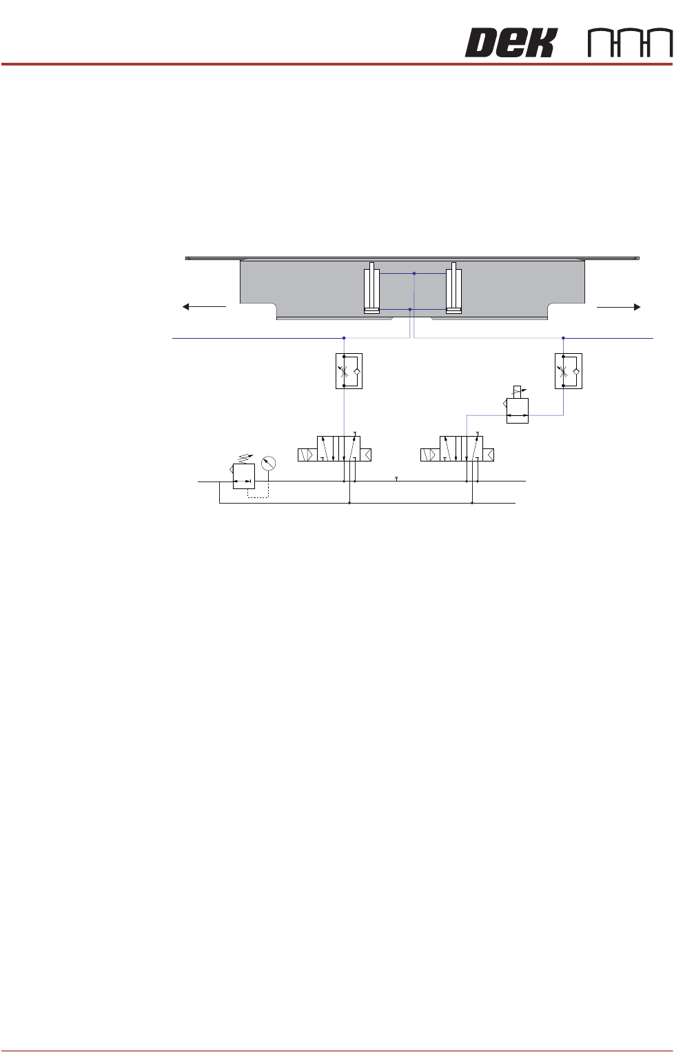
The solenoid valves (1 and 2) control two pairs of double acting cylinders in the
mid plate of the APC modules. With Valve 2 on, a software controlled air
regulator is used to proportionally control mid plate down. With Valve 1 on, it
pushes the mid plate up, when off, the balance regulator supplies low pressure
to support the weight of the APC unit. A pair of speed controllers are used to
control the speed of the mid plate up; this prevents board bounce during
unclamping. Air lines to and from the mid plate cylinders are coloured blue.
Figure 1-4 Mid Plate Pneumatics - Valves 1 and 2
Valve 1
Mid Plate Up
Valve 2
Mid Plate Down
Balance
Valve
Clamp
Pressure
In
Mid Plate Cylinders
Speed
Controller
Speed
Controller
To Rear
APC module
To Rear
APC module
Front
APC module
ALL PURPOSE CLAMPING (APC)
APC CONTROL
Chapter Issue 1 Nov 16 All Purpose Clamping (APC) Manual 1.15
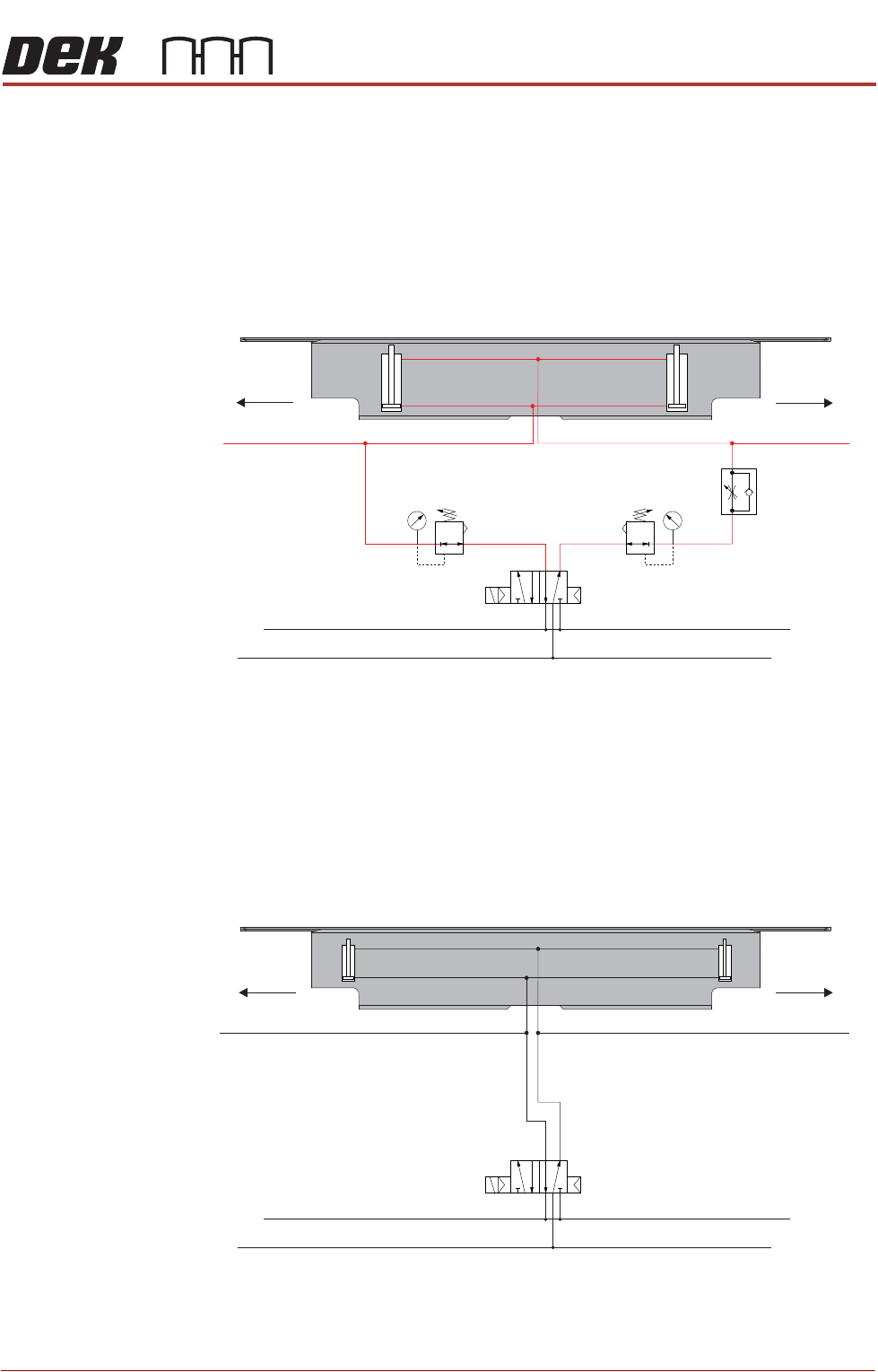
The over top plate valve (3) controls a pair of double acting slide tables which
cause the top plate to extend or retract. A pressure regulator controls each
action; the regulators are factory set and must not be adjusted. A speed
controller is employed to control the speed of the over top clamp retract
movement; this prevents board movement at the end of the clamp sequence. If
a clamping problem persists escalate it to Customer Support Group. Air lines
to and from the over top clamp cylinders are coloured red.
Figure 1-5 Over The Top Pneumatics - Valve 3
The Z clamp valve (6) controls a pair of pneumatic clamps. When on, the clamps
are activated and are used to hold and maintain the mid plate position during
printing, when off the clamps are open.
Figure 1-6 Z Clamp Pneumatics - Valve 6
Pressure
Regulator
Over Top Cylinders
Speed
Controller
To Rear
APC module
To Rear
APC module
Front
APC module
Valve 3
Over Top Clamp
Extend / Retract
Pressure
Regulator
Z Clamps
To Rear
APC module
Front APC module
Valve 6
Z Clamps
To Rear
APC module
ALL PURPOSE CLAMPING (APC)
APC CONTROL
1.16 All Purpose Clamping (APC) Manual Chapter Issue 1 Nov 16
Software
Controlled Air
Regulator
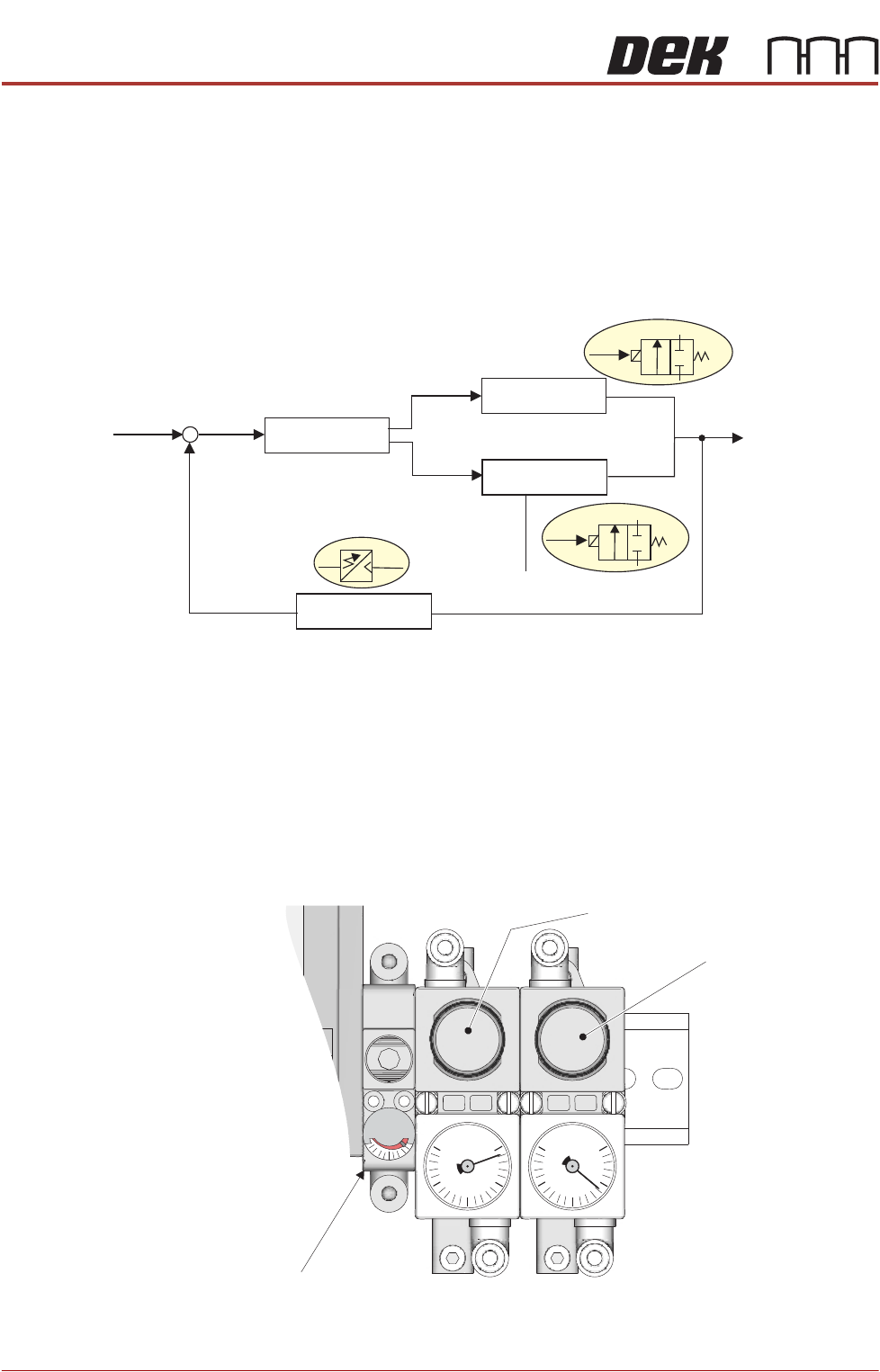
The software controlled air regulator takes electrical inputs and converts them
to a proportional pressure output. The output is dependent upon the upper level
set at the machine input supply solenoid.
The valve comprises a control circuit which performs the voltage/pressure
conversion, an exhaust valve which discharges excess air pressure, an air
supply valve which controls the output pressure for the specific function and a
pressure sensor which provides feedback to the control circuit.
In the APC system, the clamp pressure function is programmable; for details on
how to set these, refer to the APC Software chapter of this manual.
Pneumatic
Regulators
Three pneumatic regulators are employed to regulate the pressure for the
following functionality:
• Top clamp extend pressure
• Top clamp retract pressure
• Mid plate balance
-
Control Circuit
Air Supply
Valve
Out
Out
Exhaust Supply
Valve
Discharge
Input Signal
Output Pressure
Pressure Sensor
+
Top Clamp Extend
Pressure Regulator
Top Clamp Retract
Pressure Regulator
Mid Plate Balance Regulator
0
0.1
0.2
0.3
0.4
MPa
0
0.1
0.2
0.3
0.4
MPa
MPa
0
0.5
View on Pneumatic Manifold