APC - 224650 Issue 1.pdf - 第19页
ALL PURPOSE CLAMPING (APC) OPERATIONAL MODE SEQUENCES Chapter Issue 1 Nov 16 All Purpose Clamping (APC) Manual 1.7 OPERA TIONAL MODE SEQUENCES The APC has three operational modes; Snug, Clamp and Snug and Clamp. The foll…
ALL PURPOSE CLAMPING (APC)
OVERVIEW
1.6 All Purpose Clamping (APC) Manual Chapter Issue 1 Nov 16
Pneumatic
Manifold and
Node 5
The pneumatic manifold assembly contains the module regulators, operational
valves and driver board for all APC pneumatic functions. See the APC Control
section for more detail.
Magnetic Tooling
Pins
Tooling pins used on modular transport rail (MTR) machines, have a lower
shoulder than standard tooling pins. Magnetic tooling pins (p/n 112069) must
not be used on machines fitted with MTR rail systems. The tooling pins used
for MTR systems (p/n 202582, 217328 or 217329) may be used on all transport
rail systems.
CAUTION
MAGNETIC TOOLING PINS. Clash damage may occur if the incorrect tooling
pins are used on modular transport rail (MTR) printers.
ALL PURPOSE CLAMPING (APC)
OPERATIONAL MODE SEQUENCES
Chapter Issue 1 Nov 16 All Purpose Clamping (APC) Manual 1.7
OPERATIONAL MODE SEQUENCES
The APC has three operational modes; Snug, Clamp and Snug and Clamp. The
following sections detail the movements and events that form the operational
mode sequence.
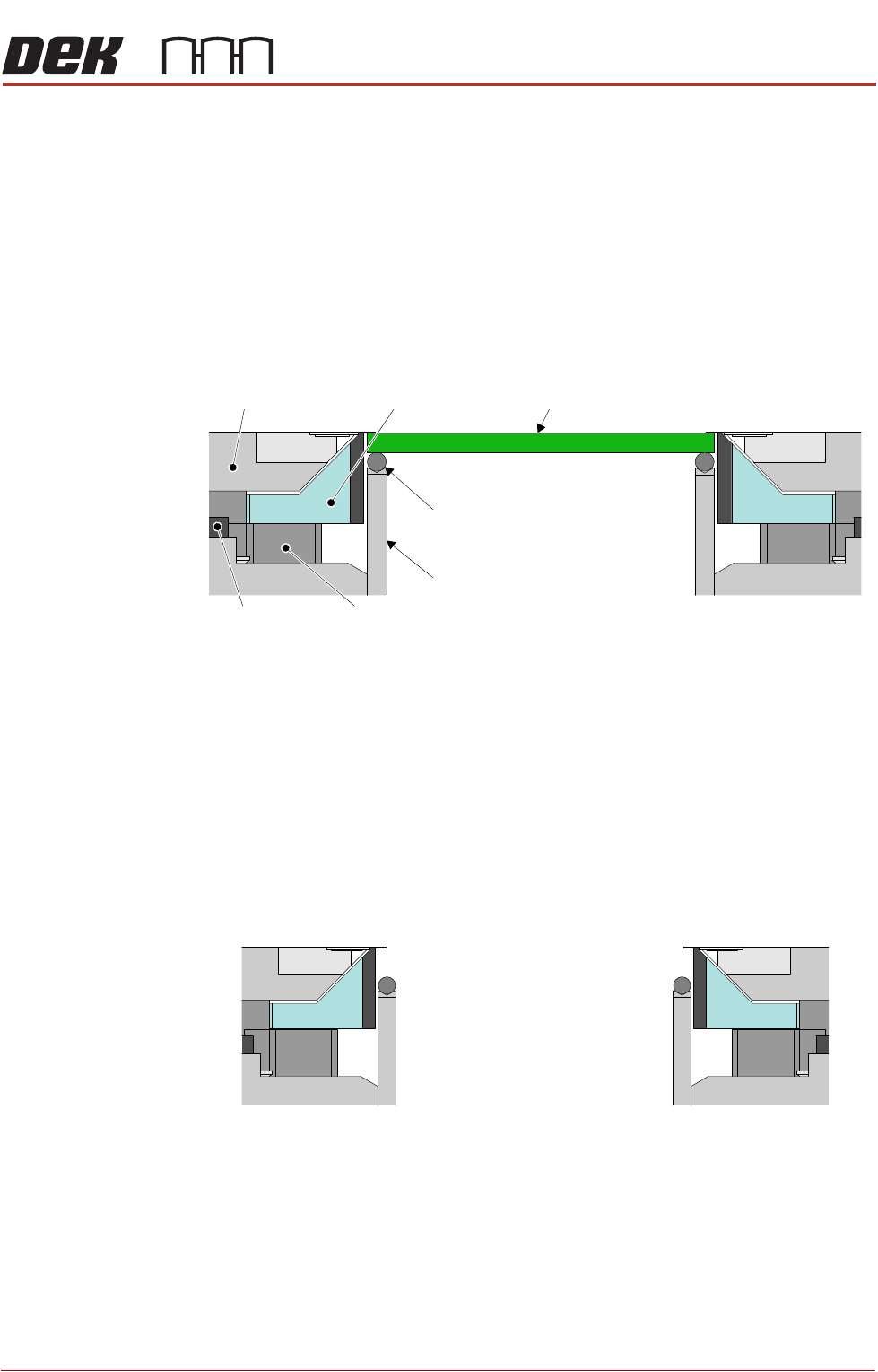
In the sequences that follow, the diagrams show the top clamp plate, the
snugger plate, Z clamp, mid plate, the board, the transport belt and the board
support. The top clamp is capable of two independent actions: in/out movement
and up/down movement (in tandem with the internal mid plate). The snugger
plate is part of the complete assembly that includes the mid plate and clamps.
Figure 1-3 Key to Operational Mode Sequence Diagrams
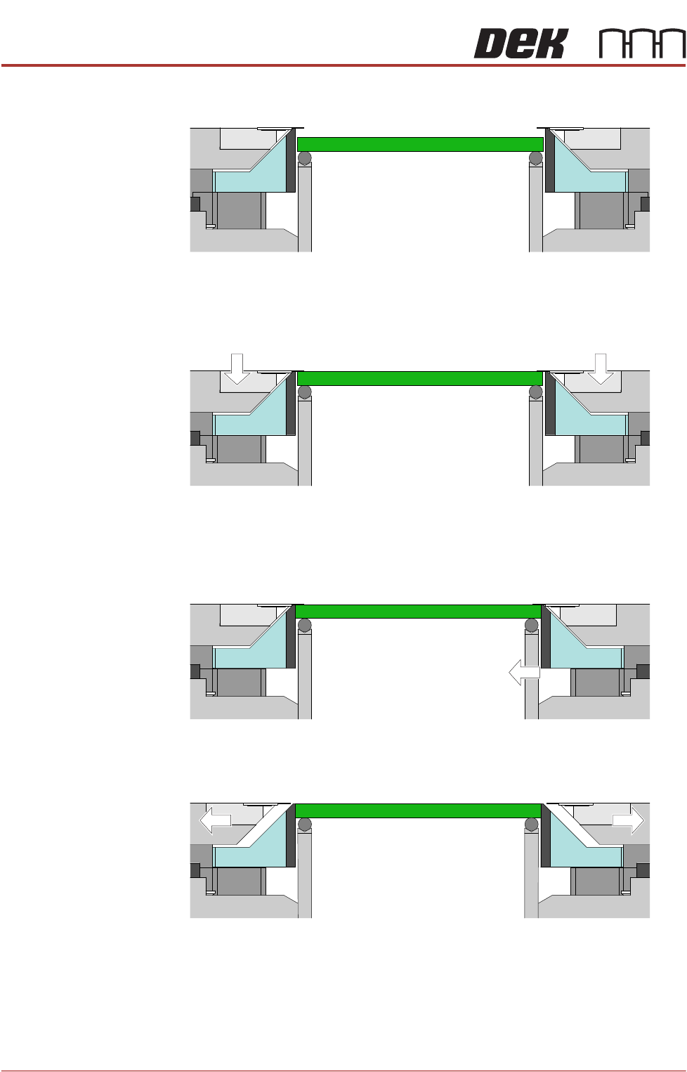
Snug Mode The Snug mode operational sequence is as follows:
1. The starting state of the APC module:
a. Top clamps are extended.
b. Mid plates are up.
c. Snug off
d. Z clamps off.
Board
Snugger Plate
Transport Belt
Belt Support Plate
Top Clamp Plate
Mid Plate
Z Clamp
Front APC Module
Rear APC Module
ALL PURPOSE CLAMPING (APC)
OPERATIONAL MODE SEQUENCES
1.8 All Purpose Clamping (APC) Manual Chapter Issue 1 Nov 16
2. The board arrives at the board stop, on the transport belts.
3. The top clamps lower, temporarily holding the board in place against the
belts and board supports, to prevent movement issues when the snugger
activates. The mid plates are locked in position by the Z clamps.
4. Snug On - the rear rail moves forward to snug the edge of the board
(maximum forward movement is 2mm, a movement of more than this results
in a Board Dropped error).
5. The top clamps retract, leaving the board snugged only.
Machine performs a print cycle - the rising table moves the rails up to print
height, the PCB board is printed, and the rails are returned to transport
height.