APC - 224650 Issue 1.pdf - 第64页
ALL PURPOSE CLAMPING (APC) REPLACEMENT PROCEDURES 1.52 All Purpose Clamping (APC) Manual Chapter Issue 1 Nov 16 Sliding Actuator Replacement There are two sliding actuators per APC module, if replacement is required then…
ALL PURPOSE CLAMPING (APC)
REPLACEMENT PROCEDURES
Chapter Issue 1 Nov 16 All Purpose Clamping (APC) Manual 1.51
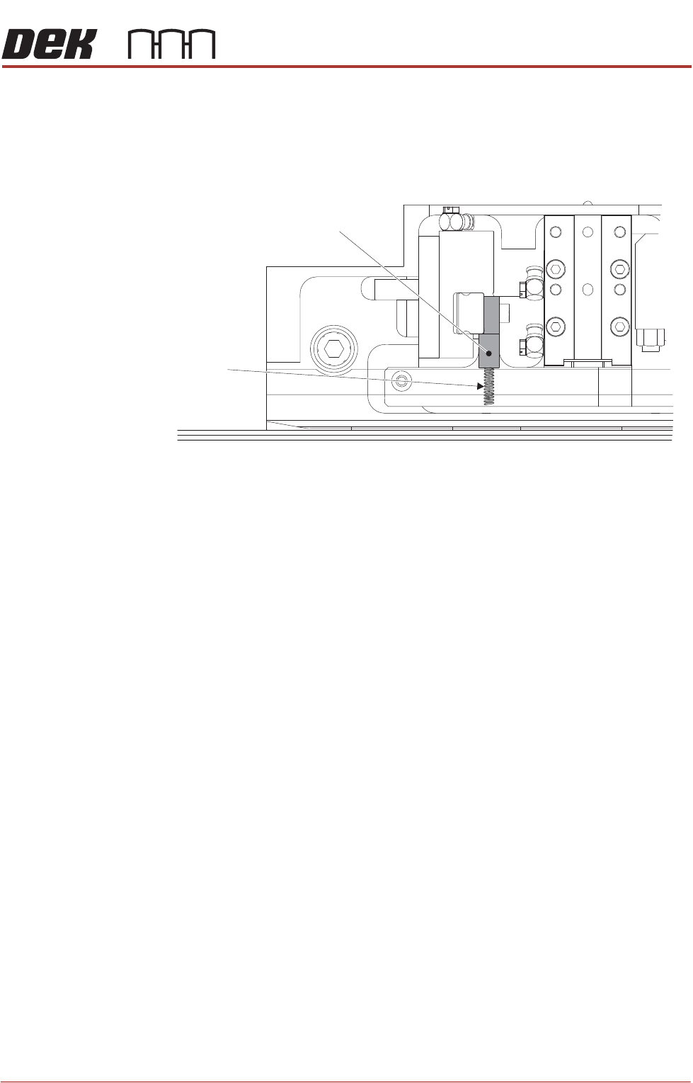
2. Install the springs into the pockets located on the rear of the snug bar.
3. Lower the snug bar into position, carefully compressing the springs so that,
when released, they extend out against the up-stand of the mid plate.
4. Apply thread lock compound to the shoulder screw. Install and tighten
shoulder screw to fix the snug bar to the mid plate.
5. Ensure that the snug bar is able to pivot on its central point
6. Install the top plate as detailed in Top Plate Replacement - Replace.
7. Install the board clamp foil as detailed in Board Clamp Foil Replacement -
Replace.
8. Complete the After Replacement Procedures.
Partial Plan View of Rear APC Module
(Snug Bar is opaque for clarity)
Spring
Up-Stand
ALL PURPOSE CLAMPING (APC)
REPLACEMENT PROCEDURES
1.52 All Purpose Clamping (APC) Manual Chapter Issue 1 Nov 16
Sliding Actuator
Replacement
There are two sliding actuators per APC module, if replacement is required then
both actuators in a module should be replaced as a pair.
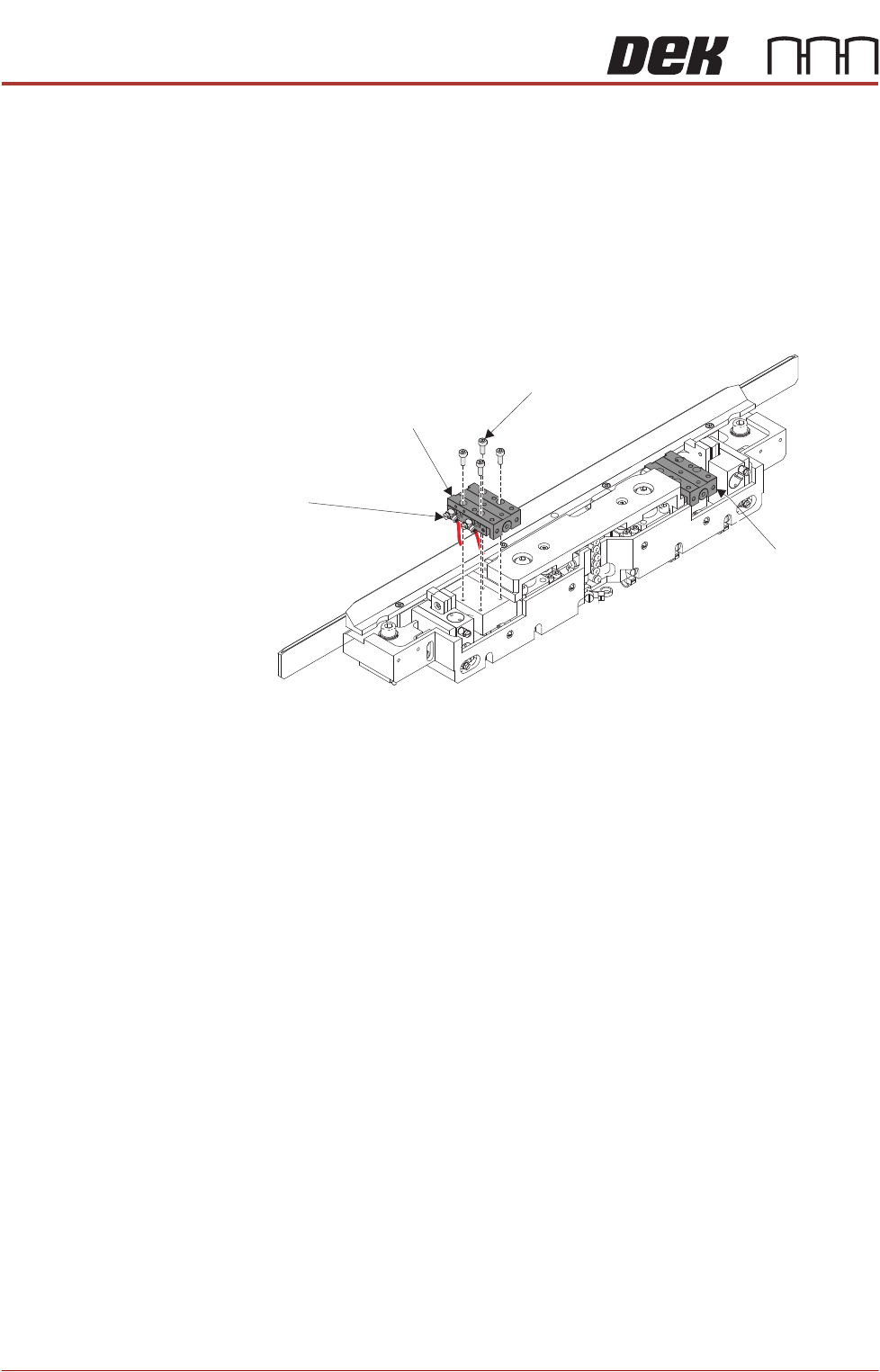
Remove 1. Ensure the Prepare for Replacement procedure has been completed.
2. Remove the board clamp foil, as detailed in Board Clamp Foil Replacement
- Remove.
3. Remove the top plate, as detailed in Top Plate Replacement - Remove.
4. Using a 2.5mm Allen key, remove the cap head screws from the first slide
table.
5. Partially remove the slide table to gain access to the pneumatic elbow
fittings.
6. Make a note of the elbow fittings orientation to aid with installation of new
slide table.
7. Using a small flat bladed screwdriver, remove the pneumatic elbow fittings.
8. Remove the slide table.
9. Repeat Steps 4 to 8 for the other slide table.
Slide Table
Cap Head Screw
(4 positions)
Pneumatic Elbow Fittings
(2 positions)
Slide Table
ALL PURPOSE CLAMPING (APC)
REPLACEMENT PROCEDURES
Chapter Issue 1 Nov 16 All Purpose Clamping (APC) Manual 1.53
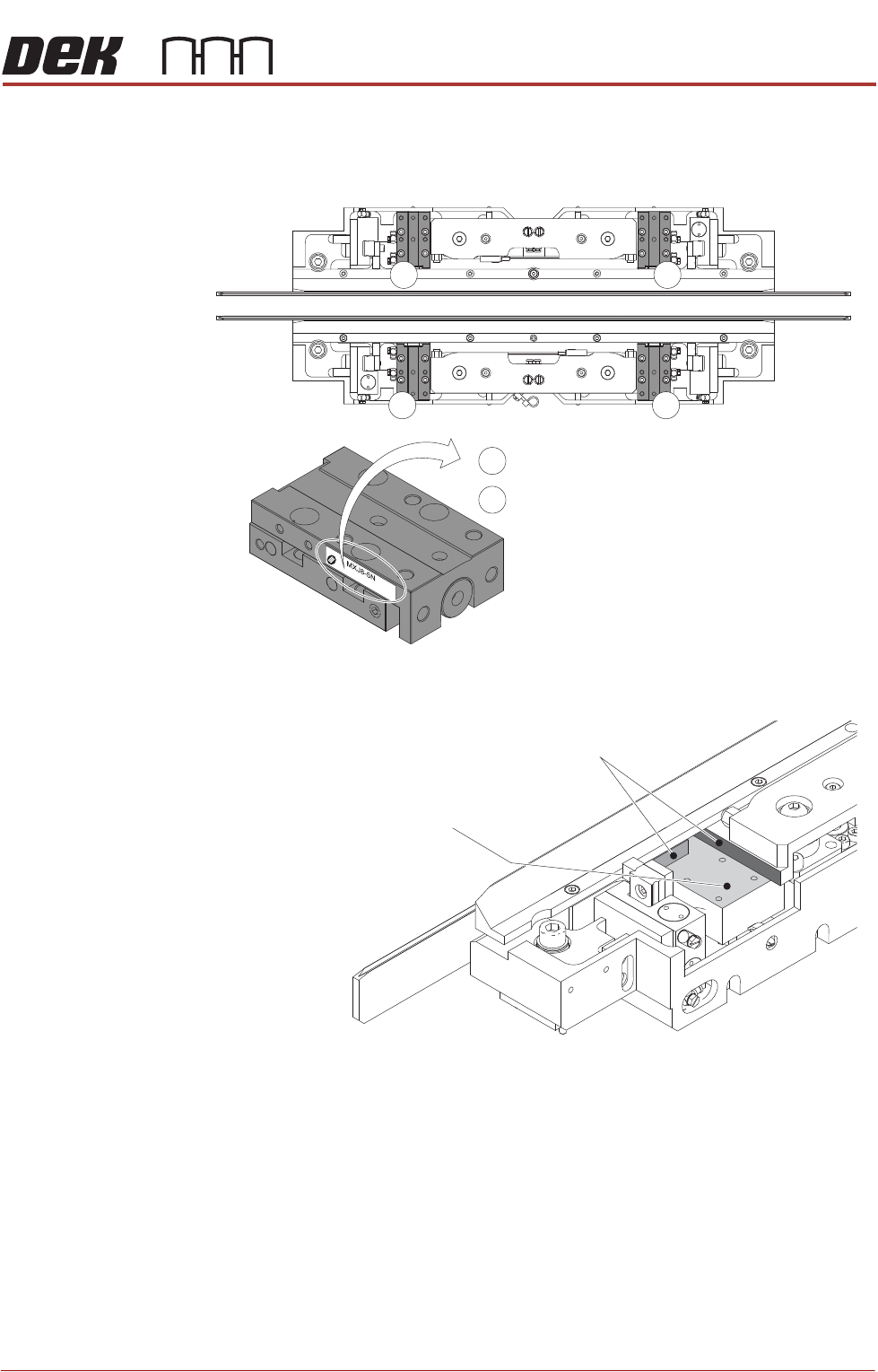
Replace 1. Identify the correct slide table assemblies for replacement, the following
illustration shows the correct assembly model numbers and how to deter
-
mine them.
2. Using IPA wipes, clean the mounting/datum faces on the mid plate.
3. Using a small flat bladed screwdriver, install the 2 pneumatic fittings to the
new slide table, in the same position and orientation as noted during the
removal procedure.
4. Position the slide table on the mounting surface.
5. Apply thread lock compound to the 4 M3 cap head screws, and loosely
attach the slide table to the mounting surface of the mid plate.
6. Ensuring that the slide table is firmly pushed up against the datum faces,
tighten the 4 M3 cap head screws.
7. Repeat Steps 2 to 6 for the other slide table.
8. Install the top plate as detailed in Top Plate Replacement - Replace.
Front
Rear
2
2
1
1
1
2
= MXJ8-5N
= MXJ8L-5N
Slide Table Mounting Surface
Slide Table Datum Faces