APC - 224650 Issue 1.pdf - 第17页
ALL PURPOSE CLAMPING (APC) OVERVIEW Chapter Issue 1 Nov 16 All Purpose Clamping (APC) Manual 1.5 The MTR system has a programmable wid t h conveyor system, set by the board width p arameter , in the product file. The rai…
ALL PURPOSE CLAMPING (APC)
OVERVIEW
1.4 All Purpose Clamping (APC) Manual Chapter Issue 1 Nov 16
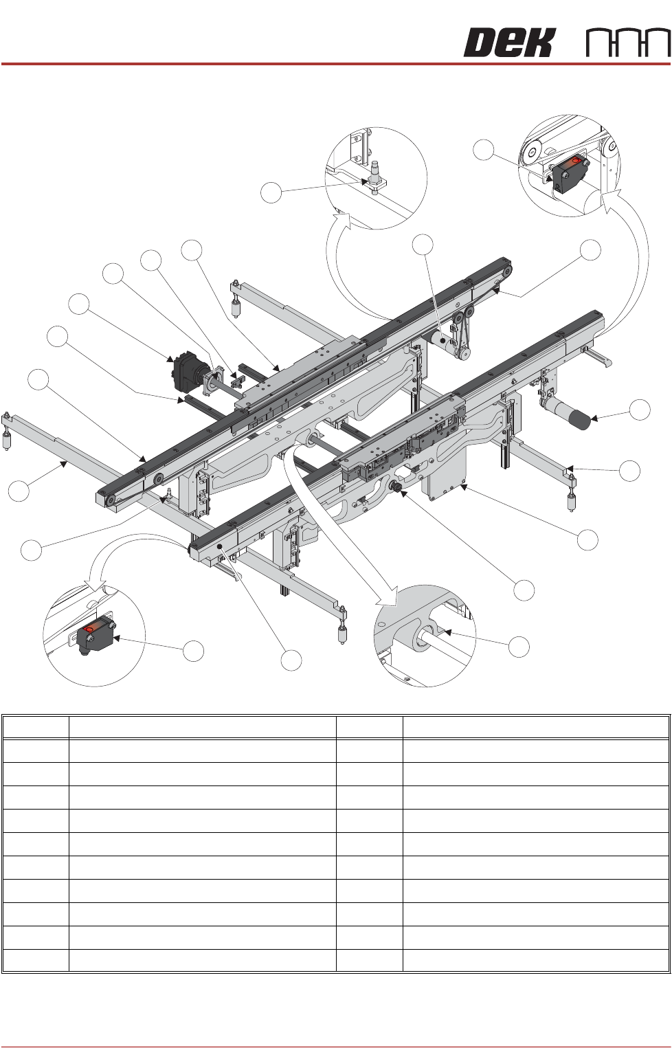
Modular Transport Rails (MTR)
Item Description Item Description
1 Board at Right Sensor 11 Left Clatter Bar
2 Transport Belts (2 positions) 12 Moving Rear Rail
3 Front Transport Belt Drive Motor 13 Moving Rear Rail Linear Guide (2 positions)
4 Right Clatter Bar 14 Rail Width Drive Motor
5 Belt Drive Motor Controllers 15 Rail Width Leadscrew
6 Manual Rail Adjuster 16 Moving Rail Home Sensor
7 Moving Rail Home Vane 17 APC Module (2 positions)
8 Fixed Front Rail 18 Right Rail Lift Sensor
9 Board at Left Sensor 19 Rear Transport Belt Drive Motor
10 Left Rail Lift Sensor
12
3
5
2
4
19
6
10
13
14
15
16
8
17
18
1
7
9
11
ALL PURPOSE CLAMPING (APC)
OVERVIEW
Chapter Issue 1 Nov 16 All Purpose Clamping (APC) Manual 1.5
The MTR system has a programmable width conveyor system, set by the board
width parameter, in the product file. The rails transport the board, using belts,
from the upline machine into the printer, where the board is transferred, using
the same belts, to the downline machine.
MTR offers system modularity; the centre section, which holds and locates the
product, can be removed to accomodate any future upgrades, without having
to replace the complete transport system.
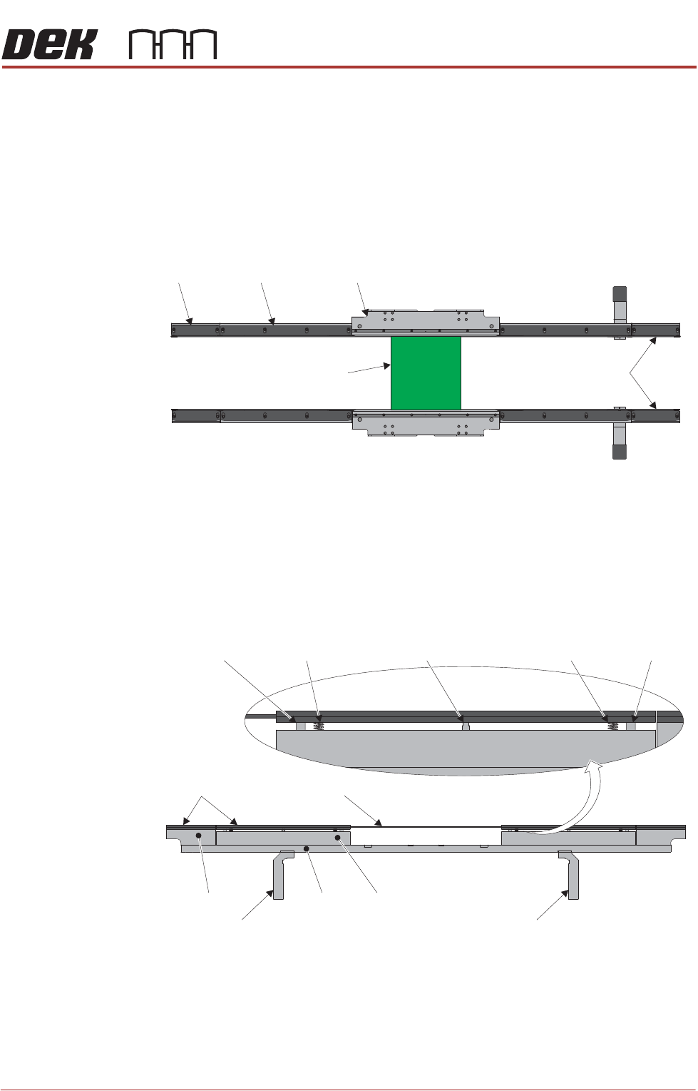
The transport rails have three sections; end rails, mid rails and centre section.
End and Mid Rails In both end and mid sections, there are two screws under the board guide which
attach the rail body to the chassis. The chassis is attached to the rising tables
rail support by the transport legs.
During board transport the mid rail board guide lifts; for printing, the mid rail
board guide lowers. A pneumatically driven piston is used to lower the board
guides; the mid rail screws have an outer guide sleeve fitted to allow this
movement. Two springs raise the guides to the transport (up) position.
Centre Section The centre section is used for holding the product securely during printing. This
section is modular, and it is designed to allow for a variety of clamping arrange
-
ments. Currently, the centre section houses the APC arrangement.
Modular Transport Rails Top View
End Rail
Mid Rail
Centre Section - All Purpose Clamping Module
Board
Transport Belts
Board Guides
Transport Leg
End Rail
Chassis
Mid Rail
Transport Belt
Guide Sleeve
Pull Down Piston
Spring
Transport Leg
Modular Transport Rails Side View
Guide Sleeve
Spring
ALL PURPOSE CLAMPING (APC)
OVERVIEW
1.6 All Purpose Clamping (APC) Manual Chapter Issue 1 Nov 16
Pneumatic
Manifold and
Node 5
The pneumatic manifold assembly contains the module regulators, operational
valves and driver board for all APC pneumatic functions. See the APC Control
section for more detail.
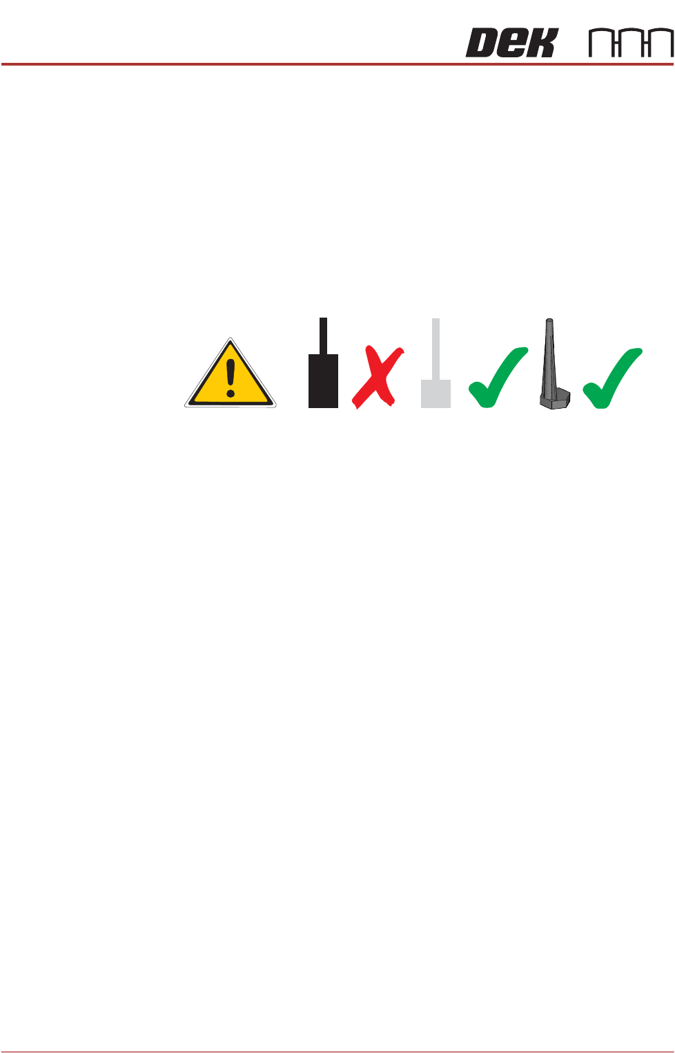
Magnetic Tooling
Pins
Tooling pins used on modular transport rail (MTR) machines, have a lower
shoulder than standard tooling pins. Magnetic tooling pins (p/n 112069) must
not be used on machines fitted with MTR rail systems. The tooling pins used
for MTR systems (p/n 202582, 217328 or 217329) may be used on all transport
rail systems.
CAUTION
MAGNETIC TOOLING PINS. Clash damage may occur if the incorrect tooling
pins are used on modular transport rail (MTR) printers.