APC - 224650 Issue 1.pdf - 第24页
ALL PURPOSE CLAMPING (APC) OPERATIONAL MODE SEQUENCES 1.12 All Purpose Clamping (APC) Manual Chapter Issue 1 Nov 16 3. The top clamp s lower , holding the boar d in place ag ainst the belts and board supports. Th e mid p…
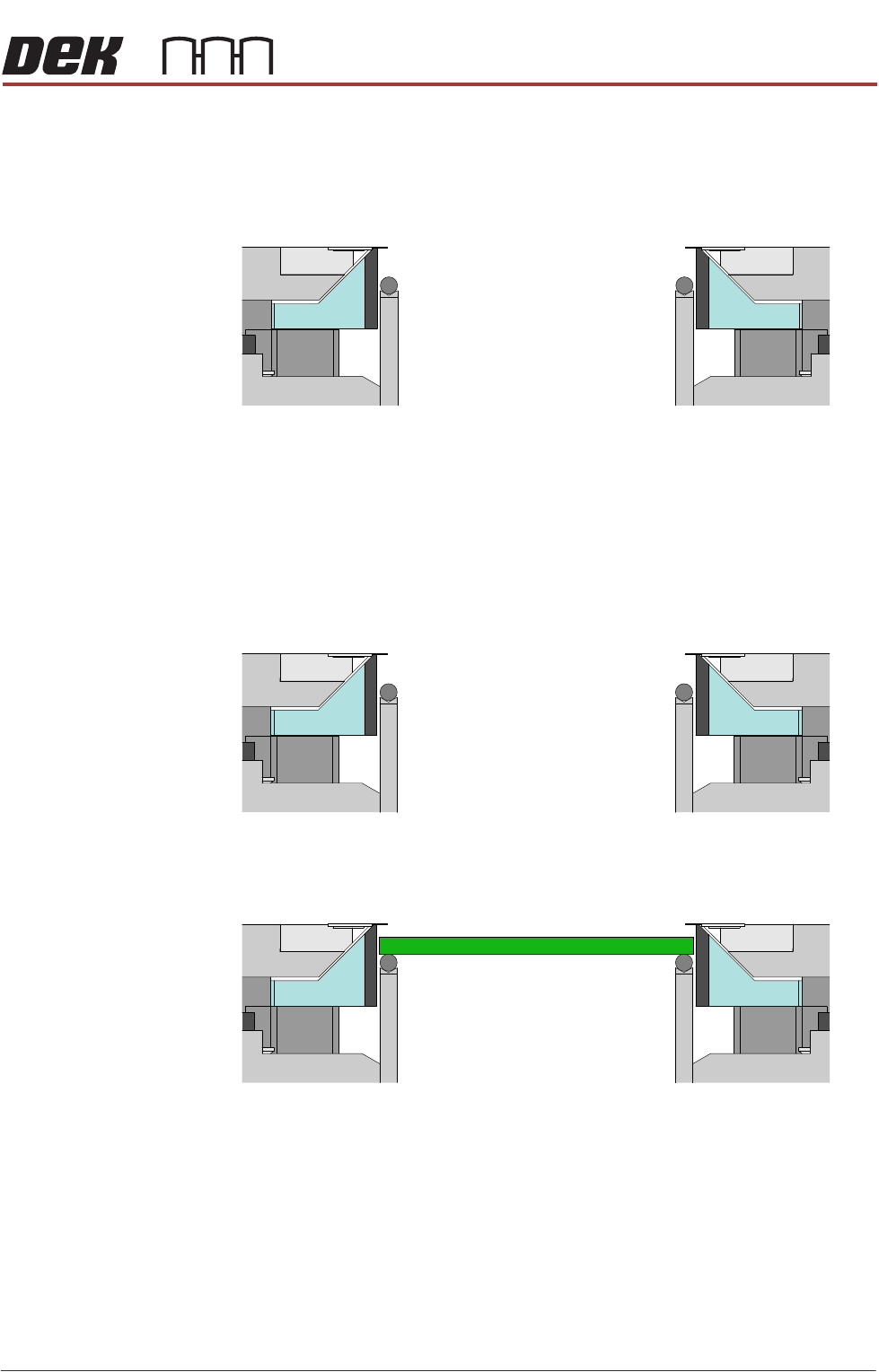
ALL PURPOSE CLAMPING (APC)
OPERATIONAL MODE SEQUENCES
Chapter Issue 1 Nov 16 All Purpose Clamping (APC) Manual 1.11
6. The mid plate/top clamps rise.
The board is fed out of the printer on the transport belts and another board
is fed in. The cycle continues until the complete batch of boards has been
printed or the print run is paused/stopped.
Clamp Mode The Clamp mode operational sequence is as follows:
1. The starting state of the APC module:
a. Top clamps are extended.
b. Mid plates are up.
c. Snug Off
d. Z clamps Off.
2. The board arrives at the board stop, on the transport belts.
ALL PURPOSE CLAMPING (APC)
OPERATIONAL MODE SEQUENCES
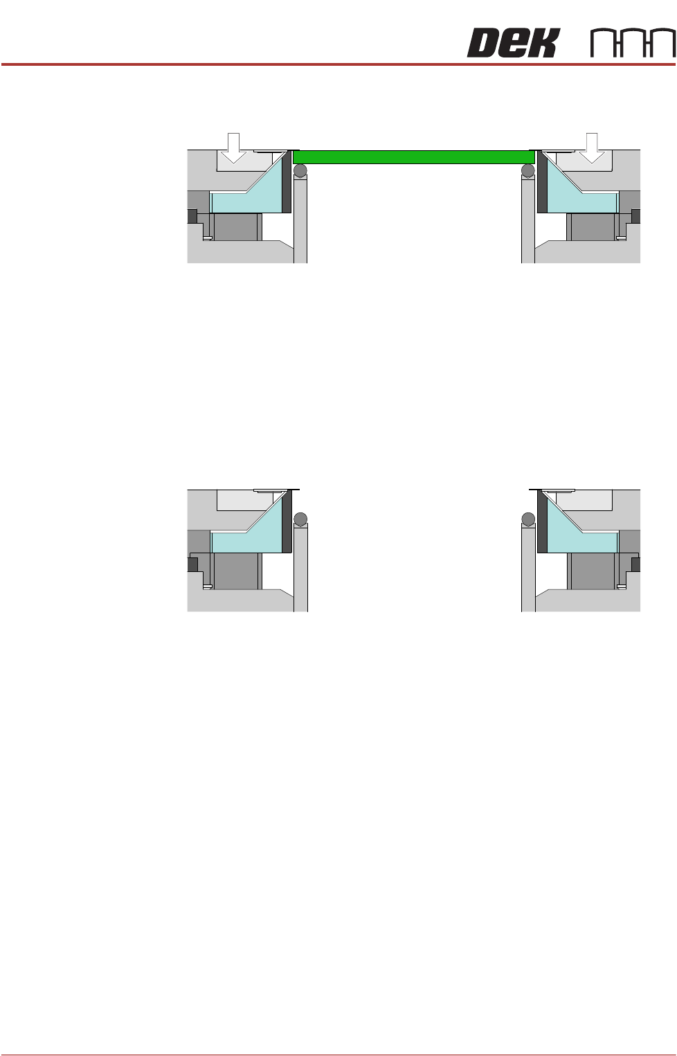
1.12 All Purpose Clamping (APC) Manual Chapter Issue 1 Nov 16
3. The top clamps lower, holding the board in place against the belts and board
supports. The mid plates are locked in position by the clamps.
Machine performs a print cycle - the rising table moves the rails up to print
height, the PCB board is printed, and the rails are returned to transport
height.
4. Z clamps Off.
The mid plate/top clamps rise.
The board is fed out of the printer on the transport belts and another board
is fed in. The cycle continues until the complete batch of boards has been
printed or the print run is paused/stopped.
ALL PURPOSE CLAMPING (APC)
APC CONTROL
Chapter Issue 1 Nov 16 All Purpose Clamping (APC) Manual 1.13
APC CONTROL
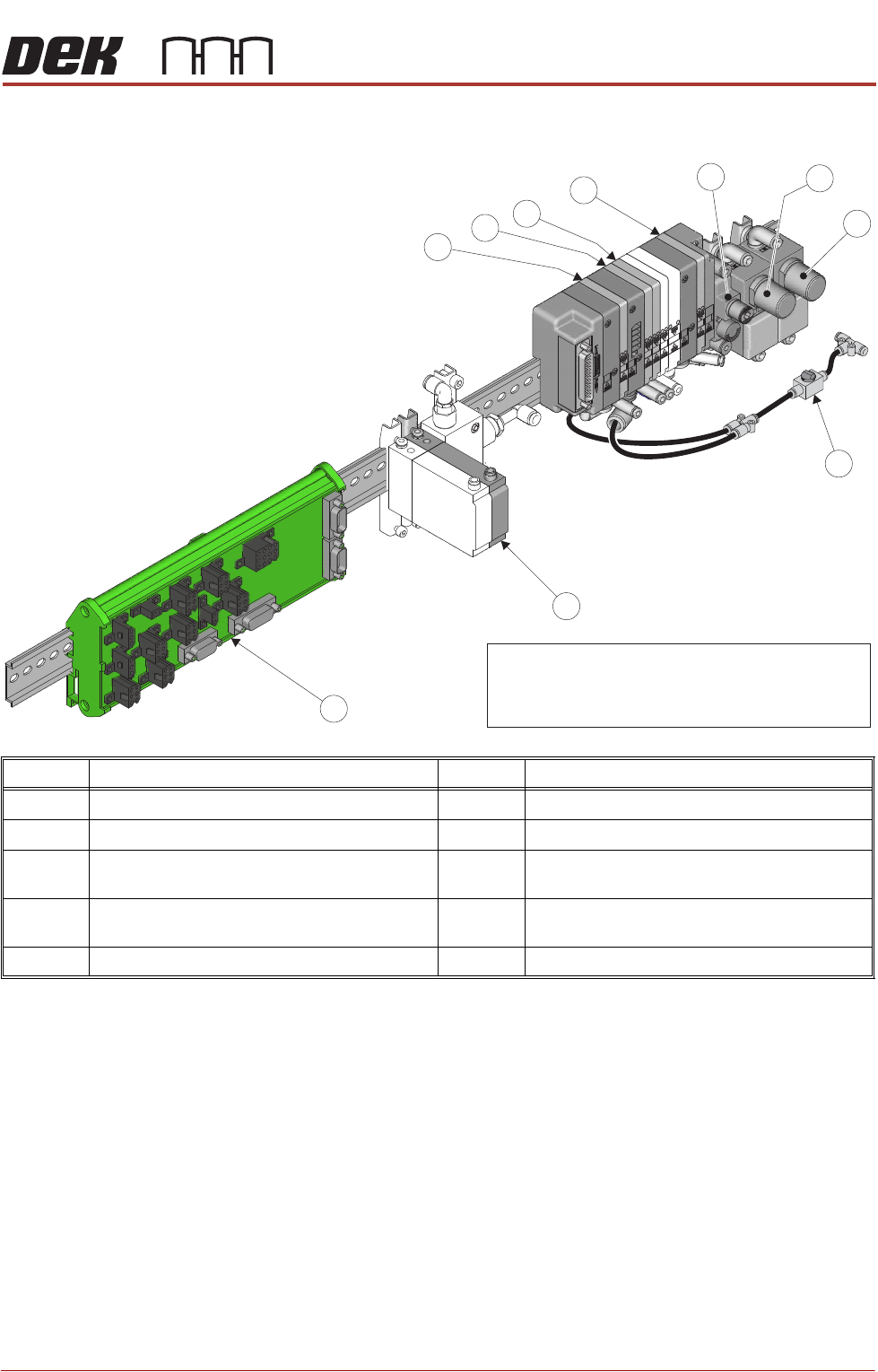
Electrical, pneumatic and electro-pneumatic control assemblies are housed at
the rear of the machine on DIN rails. The complete assembly consists of a
manifold, three pressure regulators, a software controlled air regulator, and
electrical input/output node 5. The individual components are itemised in the
drawing above.
Pneumatic
Manifold
There are four solenoid valves in the manifold they are designated as follows:
• Valve 1 - Mid Plate Up
• Valve 2 - Mid Plate Down
• Valve 3 - Over Top Plate Extend / Over Top Plate Retract
• Valve 6 - Z Clamps On / Off
Item Description Item Description
1 Mid Plate Up Valve 6 Top Clamp Extend Pressure Regulator
2 Mid Plate Down Valve 7 Top Clamp Retract Pressure Regulator
3 Overtop Plate Extend Valve /
Overtop Plate Retract Valve
8 Air Isolating Switch
4 Z Clamps Valve 9 Clamp Pressure - Software Controlled Air
Regulator
5 Mid Plate Balance Pressure Regulator 10 Node Board 5
8
9
10
7
6
5
4
3
2
1
NOTE
The sections of pneumatic manifold shown as white
are currently part of the APC manifold, but perform
no function.