APC - 224650 Issue 1.pdf - 第75页
ALL PURPOSE CLAMPING (APC) REPLACEMENT PROCEDURES Chapter Issue 1 Nov 16 All Purpose Clamping (APC) Manual 1.63 Replace 1. Using IP A wipes, clean the lif t cylinder mounting/datum faces on the base assembly . 2. Fit two…
ALL PURPOSE CLAMPING (APC)
REPLACEMENT PROCEDURES
1.62 All Purpose Clamping (APC) Manual Chapter Issue 1 Nov 16
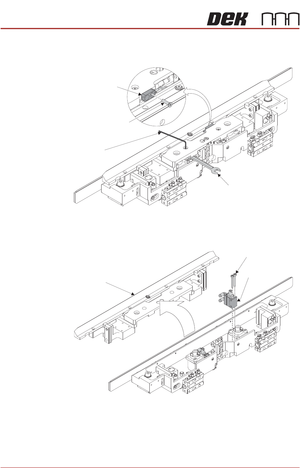
8. To allow for spanner access, slightly lift the mid plate. Using a 5.5mm A/F
spanner to prevent cylinder rod rotation, remove the lift cylinder shoulder
screws connecting the mid plate to the lift cylinders.
9. Using a 2.5mm Allen key, remove the countersunk screw securing the
sensor to the mid plate. Feed the sensor back through the clearance hole.
10. Remove the mid plate assembly.
11. Disconnect the blue pneumatic tubes from the lift cylinder’s elbow fittings,
making a note of which tube goes to which fitting.
12. Using a 2.5mm Allen key, remove the cap head screws that secure the lift
cylinder to the base assembly.
13. Remove the lift cylinder.
14. Repeat Steps 11 to 13 for the other lift cylinder.
Allen Key
5.5 A/F Spanner
Sensor
Countersunk Screw
Midplate
Assembly
Lift Cylinder
Cap Head Screws
ALL PURPOSE CLAMPING (APC)
REPLACEMENT PROCEDURES
Chapter Issue 1 Nov 16 All Purpose Clamping (APC) Manual 1.63
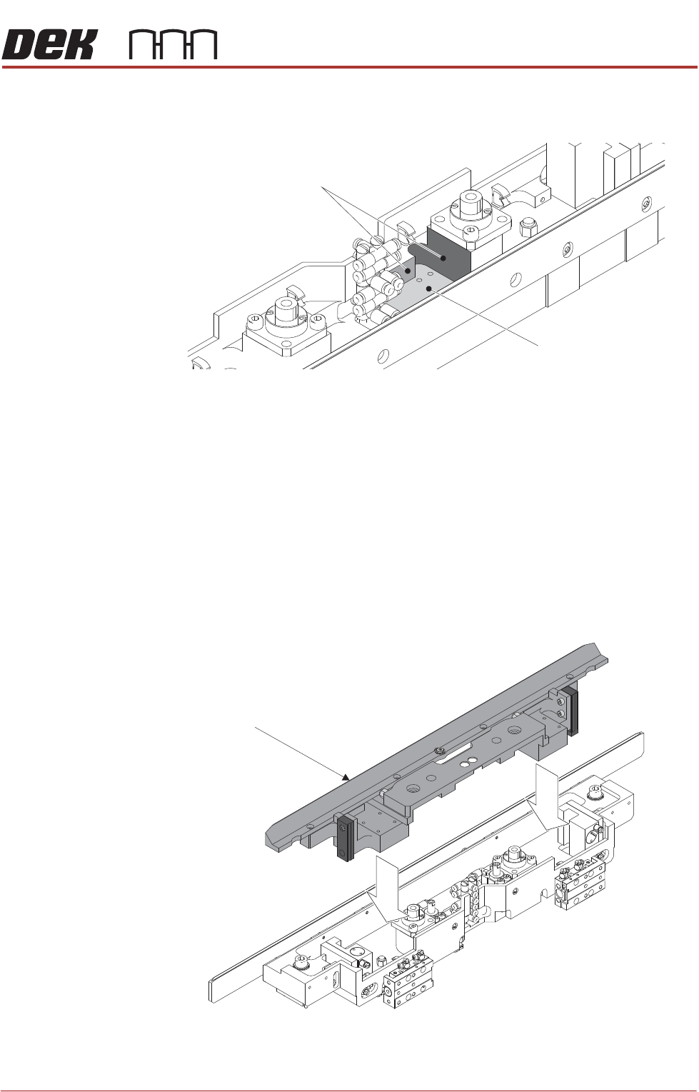
Replace 1. Using IPA wipes, clean the lift cylinder mounting/datum faces on the base
assembly.
2. Fit two elbow couplings to the lift cylinder, ensuring that the air ports will face
towards the centre of the APC module base assembly.
3. Fit the lift cylinder to the base assembly, ensuring that it is pushed in fully
against the datum faces.
4. Using a 2.5mm Allen key, secure the the lift cylinder to the base assembly
with the cap head screws.
5. Reconnect the blue pneumatic tubing, ensuring they are connected cor-
rectly as noted in Step 11 of the removal procedure.
6. Repeat Steps 2 to 5 for the other lift cylinder.
7. Install the mid plate assembly.
8. Feed the sensor back through the clearance hole. Secure the sensor to the
mid plate using a 2.5mm Allen key and countersunk screw .
Lift Cylinder
Mounting Surface
Lift Cylinder Datum Faces
Midplate
Assembly
ALL PURPOSE CLAMPING (APC)
REPLACEMENT PROCEDURES
1.64 All Purpose Clamping (APC) Manual Chapter Issue 1 Nov 16
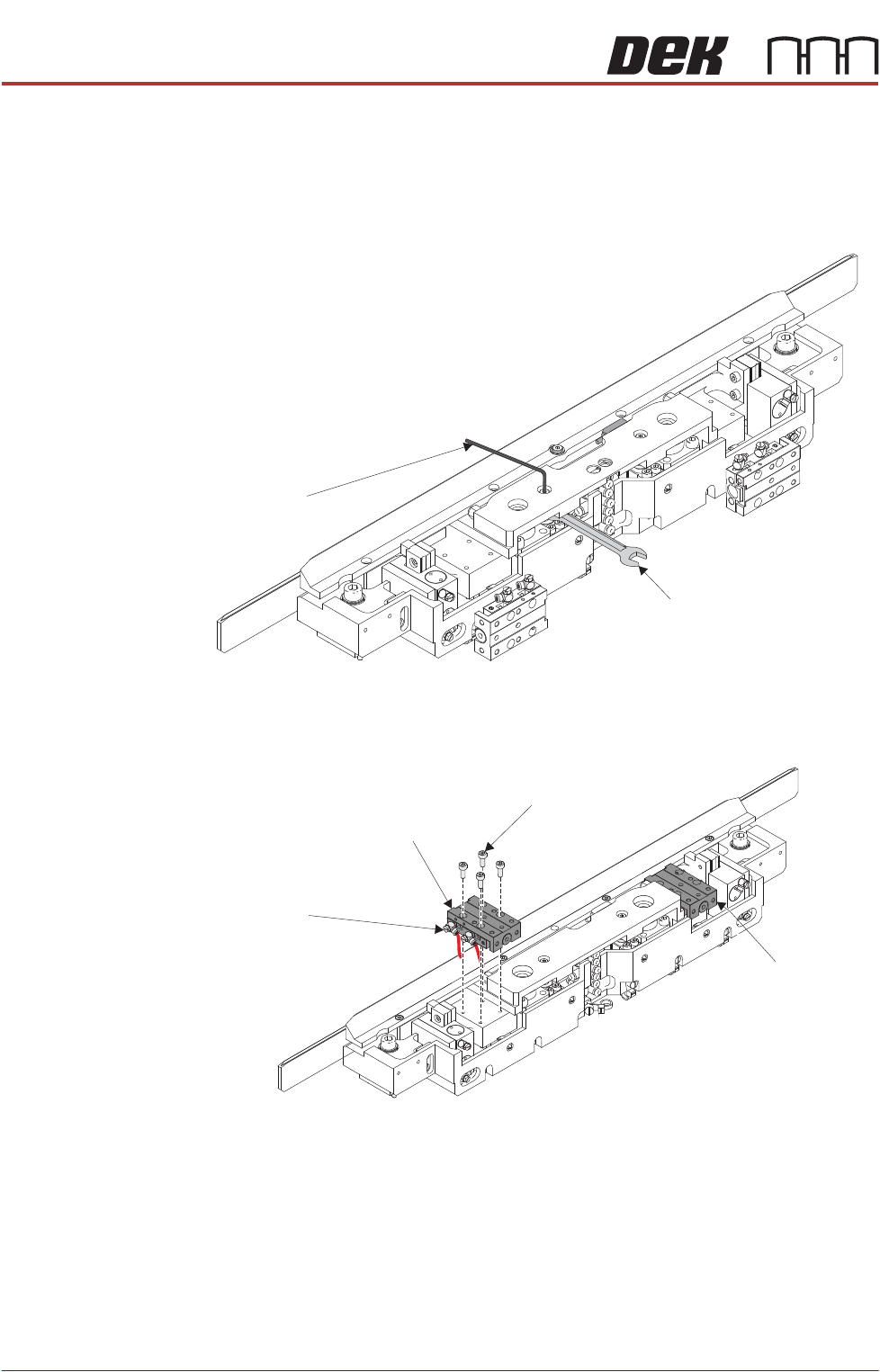
9. With the mid plate in the lowered position, install the 2 shouldered screws
and tighten until the cylinder rods start rotating.
10. To fully tighten the shouldered screws, slighty lift the mid plate. Using a
5.5mm A/F spanner to prevent cylinder rod rotation, fully tighten the lift
cylinder shoulder screws.
11. Lift the slide table, and reinstall in accordance with the Sliding Actuator
Replacement, Replace procedure Steps 2 to 7 found earlier in this section.
12. Repeat Step 11 for the other slide table.
13. Centralise the mid plate assembly in the x axis.
Allen Key
5.5 A/F Spanner
Slide Table
Cap Head Screw
(4 positions)
Pneumatic Elbow Fittings
(2 positions)
Slide Table