APC - 224650 Issue 1.pdf - 第59页
ALL PURPOSE CLAMPING (APC) REPLACEMENT PROCEDURES Chapter Issue 1 Nov 16 All Purpose Clamping (APC) Manual 1.47 10. Apply thread lock compound to th e set screw , and assemble into the rear of the top plate (do not fully…
ALL PURPOSE CLAMPING (APC)
REPLACEMENT PROCEDURES
1.46 All Purpose Clamping (APC) Manual Chapter Issue 1 Nov 16
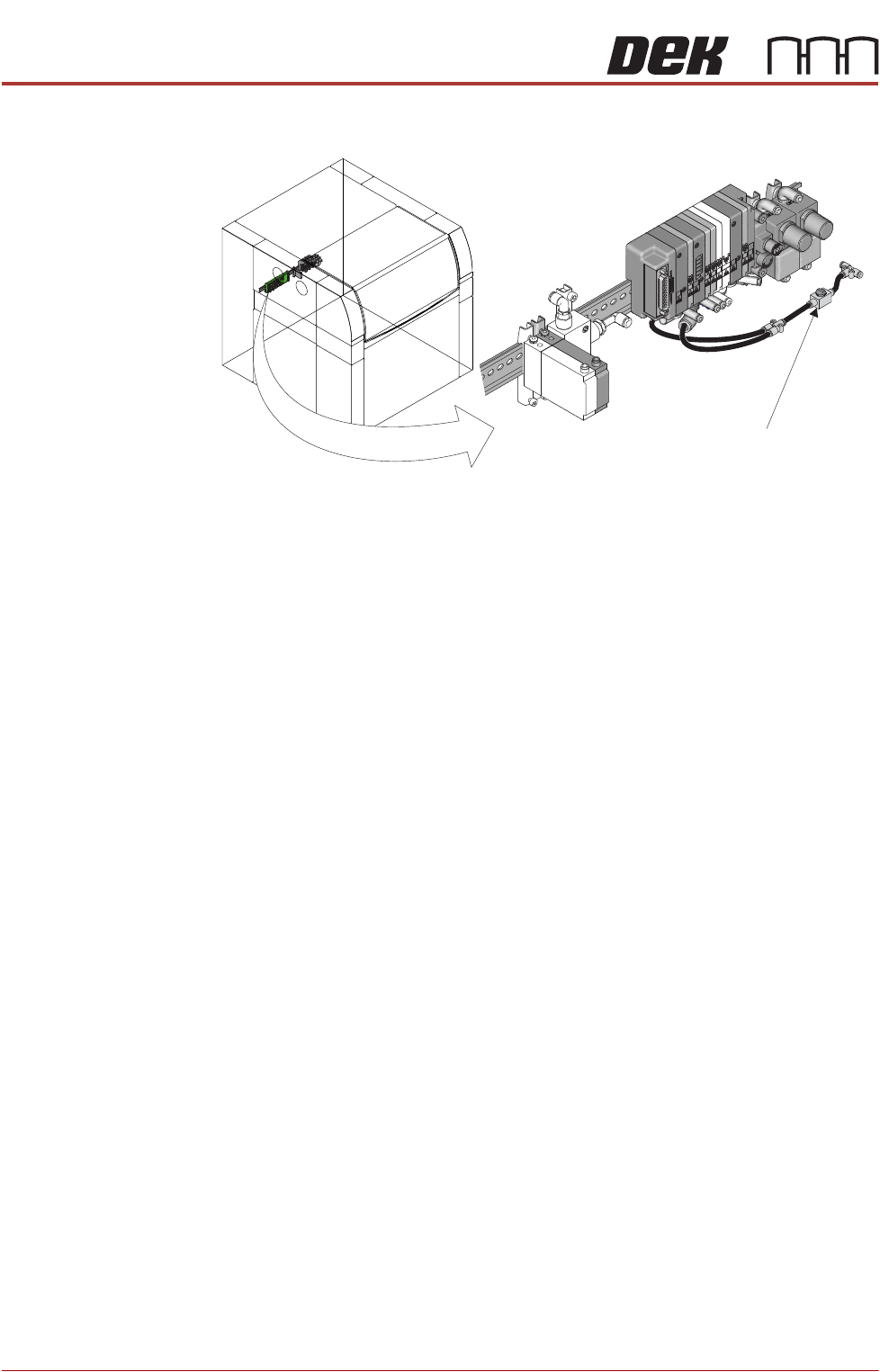
3. Use the isolator switch valve to reapply the air supply to the APC modules.
4. In Diagnostics \ Rail System, use Next or Previous to highlight Toggle
OTS Over Top Clamp.
5. Select Run Diagnost to toggle ON, so that the top clamps are retracted.
6. Tighten the 8 M3 cap head screws to 1.4Nm. Visually check that the top
plate is parallel with the base of the module.
7. Install 8 new green dust caps on top of the top plate retaining cap head
screws.
NOTE
If the top plate-sliding table position has already been setup (shown by set
screw and locknut already being fitted to top plate, and Varnistop being
present on the locknut) - proceed to Step 13.
8. In Diagnostics \ Rail System, use Next or Previous to highlight Toggle
OTS Over Top Clamp.
9. Select Run Diagnost to toggle OFF, so that the top clamps are extended.
If working on the rear APC module, ensure that the snug bar is able to pivot
on its central point.
Isolator Switch Valve
Location of APC Pneumatic Manifold
ALL PURPOSE CLAMPING (APC)
REPLACEMENT PROCEDURES
Chapter Issue 1 Nov 16 All Purpose Clamping (APC) Manual 1.47
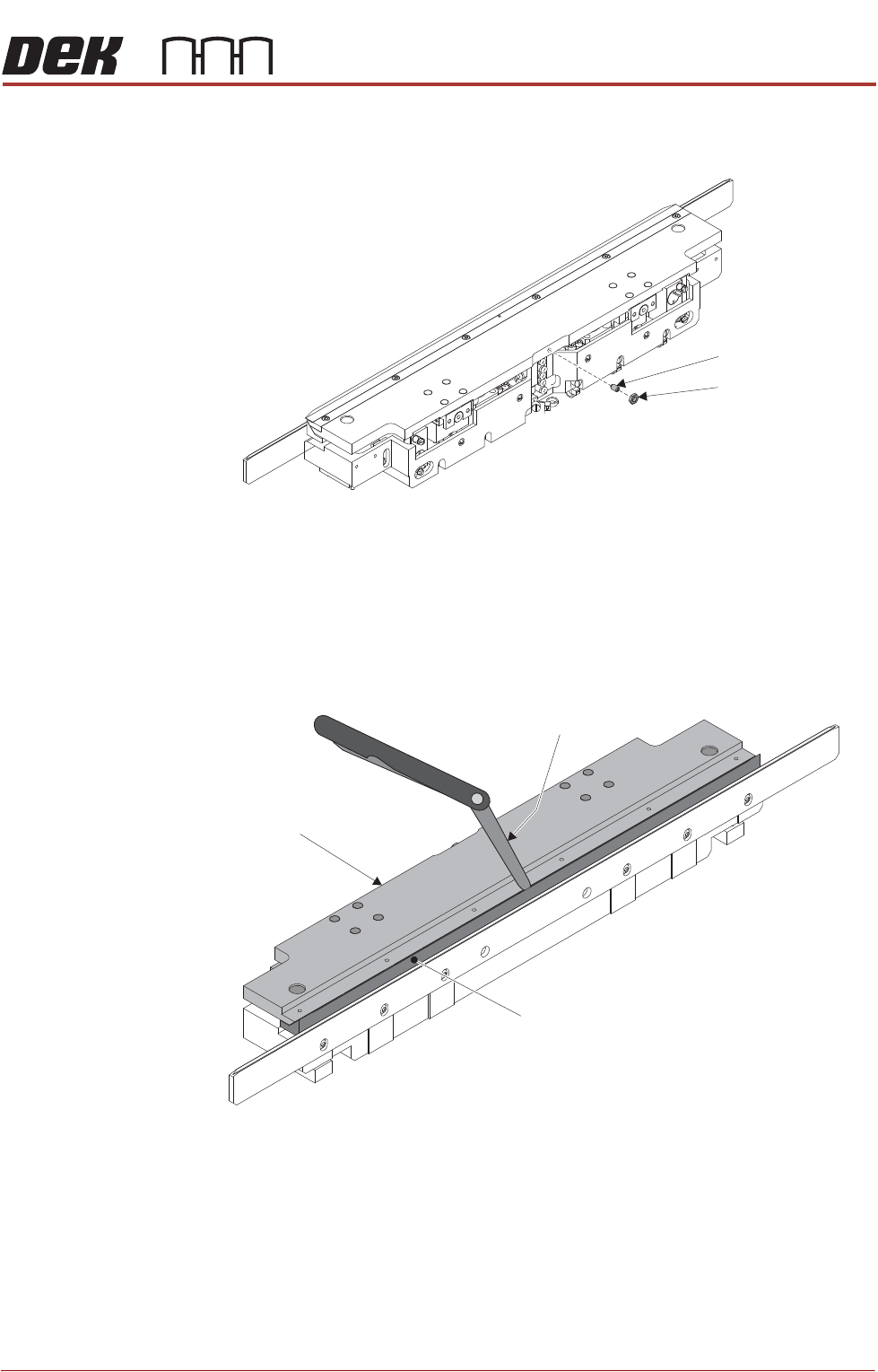
10. Apply thread lock compound to the set screw, and assemble into the rear of
the top plate (do not fully tighten).
11. While sliding a 350μm feeler gauge between the angled face of the snug bar
and the top plate, slowly tighten the set screw until the feeler gauge only just
fits. Check that a 400μm feeler gauge will not slip between the snug bar and
the top plate.
NOTE
As the rear assembly’s snug bar is fixed centrally to allow it to pivot, the
feeler gauge check can only be performed in the centre of the assembly.
12. Assemble and tighten the locknut. Check again that a 350μm feeler gauge
will slip between the angled face of the snug bar and the top plate, but a
400μm feeler gauge will not.
13. Install the board clamp foil as detailed in Board Clamp Foil Replacement -
Replace.
14. Complete the After Replacement Procedures.
Set Screw
Locknut
Top Plate
Feeler Gauge
Snug Bar
ALL PURPOSE CLAMPING (APC)
REPLACEMENT PROCEDURES
1.48 All Purpose Clamping (APC) Manual Chapter Issue 1 Nov 16
Front Snug Bar Replacement
Remove 1. Ensure the Prepare for Replacement procedure has been completed.
2. Remove the board clamp foil as detailed in Board Clamp Foil Replacement
- Remove.
3. Remove the top plate as detailed in Top Plate Replacement - Remove.
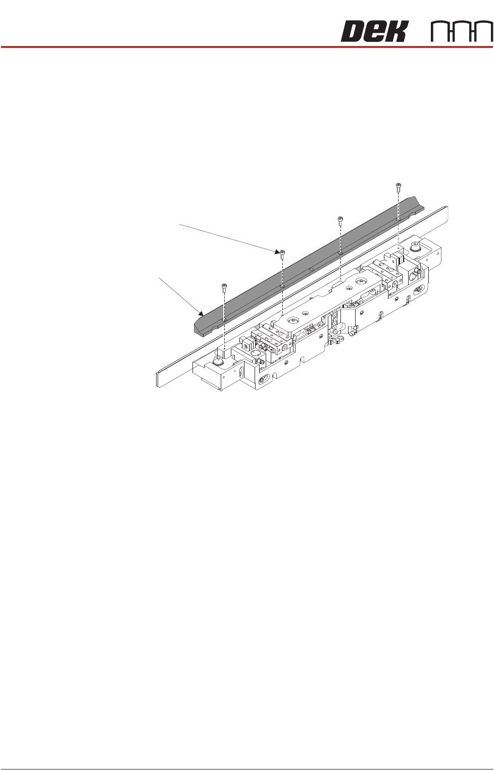
4. Using a 2.5mm Allen key, remove the cap head screws from the snug bar.
5. Remove the snug bar.
Front Snug Bar
Cap Head Screws
(4 positions)