APC - 224650 Issue 1.pdf - 第81页
ALL PURPOSE CLAMPING (APC) REPLACEMENT PROCEDURES Chapter Issue 1 Nov 16 All Purpose Clamping (APC) Manual 1.69 1 1. Use the isolator switch valve to reinst ate the air supply to the APC modules. 12. Ensure that the zimm…
ALL PURPOSE CLAMPING (APC)
REPLACEMENT PROCEDURES
1.68 All Purpose Clamping (APC) Manual Chapter Issue 1 Nov 16
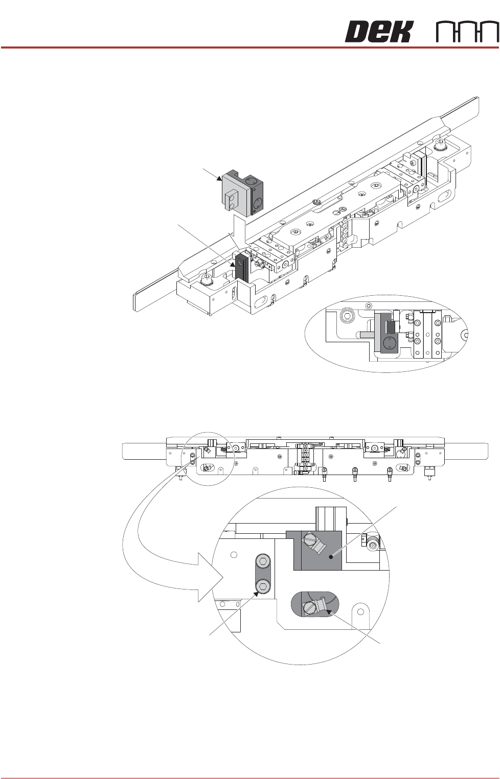
6. Install the clamp assembly into the base assembly, ensuring the assembly
slides down and surrounds the linear rail.
7. Using a 2.5mm Allen key, secure the clamp assembly to the base assembly.
8. Using a flat bladed screwdriver, reconnect the elbow fittings to the clamp
assembly. Ensure the fittings are orientated and installed to the correct ports
(noted/marked during Step 4 of the removal procedure).
9. Repeat Steps 6 to 8 for the other clamp assembly.
10. Centralise the mid plate assembly in the x axes.
Clamp Assembly
Linear Rail
Top View of Installed Clamp Assembly
Pneumatic Elbow Fitting
(2 positions)
Cap Head Screw
(2 positions)
Clamp and Clamp
Mounting Block Assy
ALL PURPOSE CLAMPING (APC)
REPLACEMENT PROCEDURES
Chapter Issue 1 Nov 16 All Purpose Clamping (APC) Manual 1.69
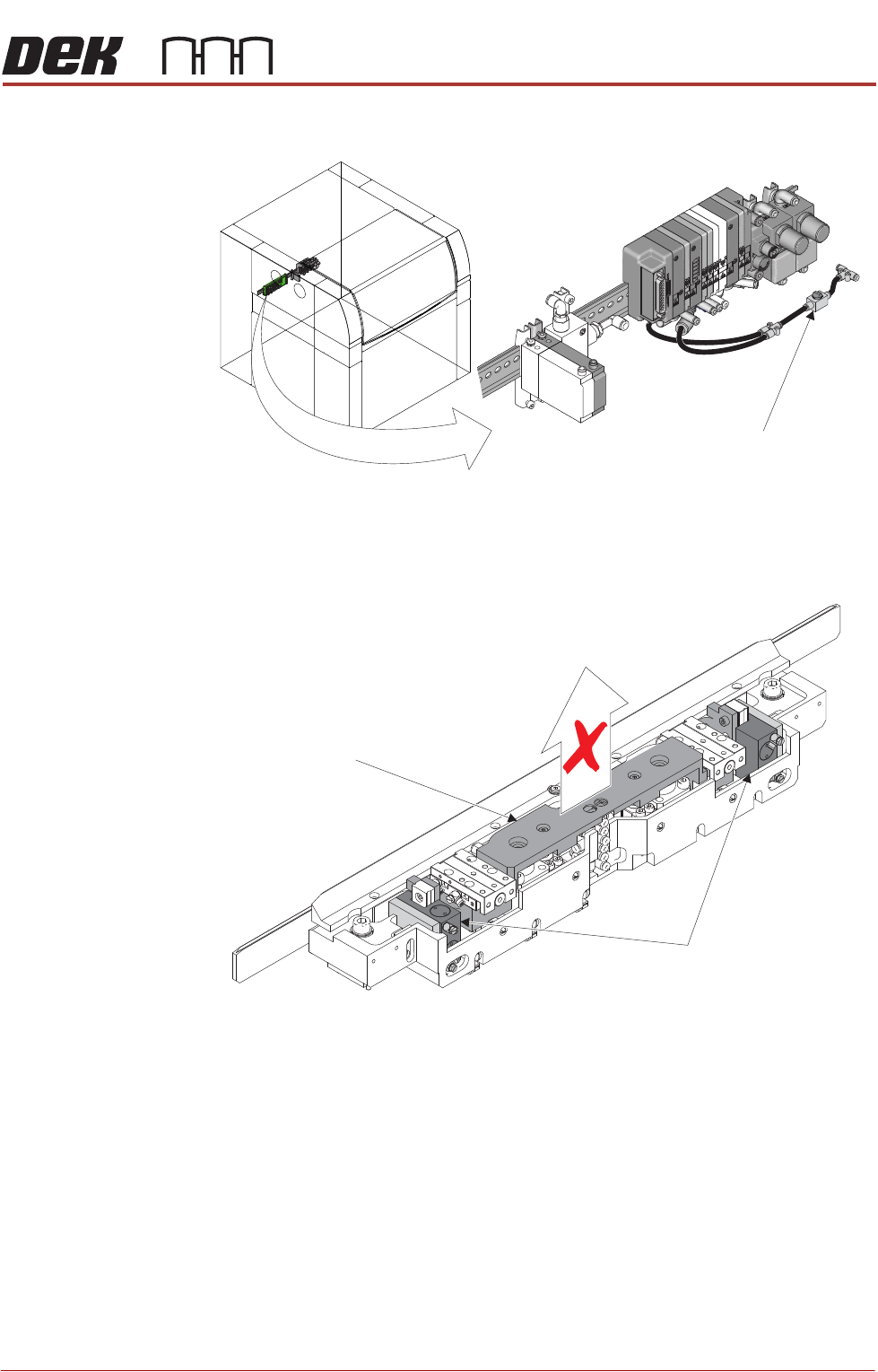
11. Use the isolator switch valve to reinstate the air supply to the APC modules.
12. Ensure that the zimmer clamps have energised. The mid plate assembly
should not be able to rise when manually lifting is attempted.
13. Using a 5mm Allen key, fully tighten the socket button head screws and shim
washers that attach the mid plate to the ball spline assemblies.
14. Use the isolator switch valve to isolate the air supply to the APC modules.
Disconnect the up-stream hose from the isolator switch to allow any residual
pressure in the system to vent. Reconnect the up-stream hose.
15. Ensure that the mid plate assembly has free movement. Lift the assembly
and allow to drop, checking that it drops under its own weight back to its
original position.
16. Install the top plate as detailed in Top Plate Replacement - Replace.
17. Install the board clamp foil as detailed in Board Clamp Foil Replacement -
Replace.
18. Complete the After Replacement Procedures.
Isolator Switch Valve
Location of APC Pneumatic Manifold
Zimmer Clamps
(2 positions)
Mid Plate Assembly
ALL PURPOSE CLAMPING (APC)
REPLACEMENT PROCEDURES
1.70 All Purpose Clamping (APC) Manual Chapter Issue 1 Nov 16
End, Centre and
Mid Rail Removal
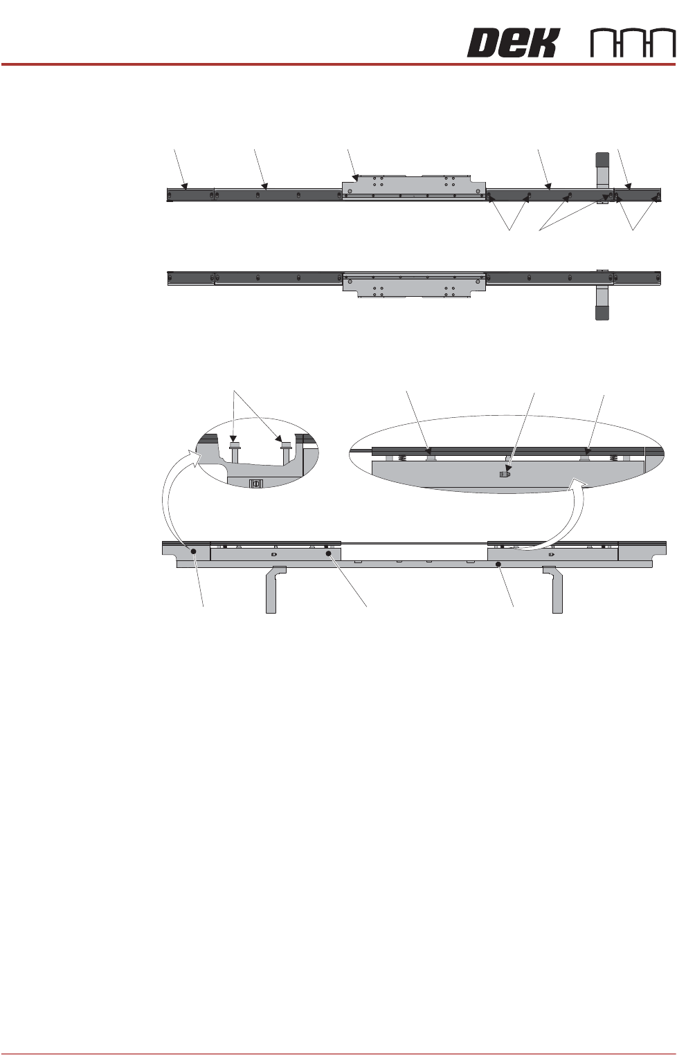
The MTR system comprises two end rails, two mid rails and a centre section
per rail.
End Rail To remove and replace an end rail:
1. Slip the transport belt off the associated end rail pulley.
2. Locate the two M3 x8mm board guide retaining screws and remove them.
3. Remove the end rail board guide.
4. Locate the two M6 x 50mm end rail screws and remove them. The end rail
is attached to the chassis and lifts free when the screws are removed.
5. Replacement is the reverse procedure (Steps 1 to 4).
6. To correctly adjust the board guide, perform the Home Position Rail Width
and Board Guide Setting procedure found in the Adjustments and Settings
section of this Chapter.
Top View
End Rail
Mid Rail
Centre Section (APC)
End Rail
Chassis
Mid Rail
Side View
(Centre Section not shown)
Mid Rail
End Rail
End Rail
Screws
Mid Rail
Screws
Mid Rail Screw
Mid Rail Screw
Pneumatic
Connection
End Rail Screws
End Rail
(Cut Away)