F5 SERVICE MAUNAL.pdf - 第112页
5 Gantries SIPLACE 80S-20/F4/F4-6/F5 Service Manual 5.1 Introduction Edition 09/99 5 - 4 5.1 Introduction 5.1.1 Safety Instructions This se ction pr ovides a descr iption of s ervicin g work on the ga ntries o f the SIPL…
SIPLACE 80S-20/F4/F4-6/F5 Service Manual 5 Gantries
Edition 09/99
5 - 3
5 Gantries
5 Gantries SIPLACE 80S-20/F4/F4-6/F5 Service Manual
5.1 Introduction Edition 09/99
5 - 4
5.1 Introduction
5.1.1 Safety Instructions
This section provides a description of servicing work on the gantries of the SIPLACE 80S-20/F
4
/F
4
-6/F
5
.
The safety instructions to be found in Section 1 will also apply to all of the servicing work described in this sec-
tion.
5.1.2 Auxiliary Materials and Equipment
You will require the auxiliary materials and equipment listed in this section for all of the servicing work carried
out on the gantries. Additional materials or equipment are listed separately in the corresponding sections.
– 1 set of screwdrivers
– 1 set of hexagon socket spanners
– 1 set of socket spanners
– 1 pair of wire cutters, small
– Screw locking varnish
– 1 digital voltmeter (class 1.5)
– Spare parts catalog SIPLACE 80S-20/F
4
/F
4
-6/F
5
– Instruction Manual ’Measuring Belt Tension’
5.1.3 General Comments
The SIPLACE 80S-20 placement machine is equipped with a pair of x-gantry and y-gantry axes which are
mechanically independent of each other. The SIPLACE 80F
4
/F
4
-6/F
5
placement machines possess one
x- and one y-gantry axis.
The SIPLACE 80S-20/F
4
/F
4
-6/F
5
gantries are of identical design. For this reason all of the servicing work
which is described in the following section will be presented on the basis of just one gantry.
The x and y axes are powered by direct current servo motors.
The position measurement system uses linear scales. For the x and y directions these are fixed directly to the
gantry axes. A read head scans the linear scales and in this way determines the position of the axis. This pro-
cedure is referred to as direct position measurement.
Power is transmitted from the direct current motors to the gantries via toothed belts and deflection.
SIPLACE 80S-20/F4/F4-6/F5 Service Manual 5 Gantries
Edition 09/99 5.1 Introduction
5 - 5
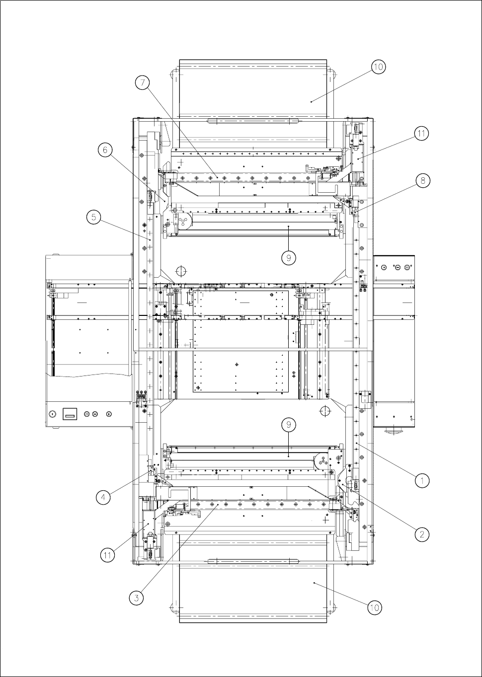
Fig. 5.1.1 General view of gantry from above: 80S-20 placement system