F5 SERVICE MAUNAL.pdf - 第466页
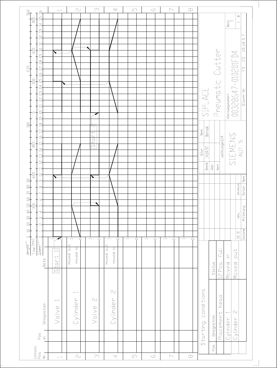
Service Manual SIPLACE 80S-2 0/F4/F5 14 Pneumatic Cut ter Edition 04/98 14.1 Pneumatic Cutter and Empty-Tape Duct 14 - 8 14.1.7 Moving Stationary and Mo vable Blades 180 ° The cutter remains installed i n the ma chine . …

Service Manual SIPLACE 80S-20/F4/F5 14 Pneumatic Cutter
Edition 04/98 14.1 Pneumatic Cutter and Empty-Tape Duct
14 - 8
14.1.7 Moving Stationary and Movable Blades 180 °
The cutter remains installed in the machine.
DANGER O O O
Comply
VWULFWO\
with the instructions in the DANGER text in Section 14.1.1.
NOTE
The movable blade has a
FXWWLQJHGJHRQERWKVLGHV
When one cutting edge becomes worn, the blade is
turned 180 °, inserted and continues to be used. When this is done, the stationary blade must
DOVR
be rotated
180 ° and installed.
When both edges have been used, i.e., are dull, proceed as described in Section 14.1.8.
14.1.7.1 Removing of the Blade
● Move the appropriate feeder changeover table out of the machine or (in case of F4/F5) dismantle the com-
ponent table and remove the component table..
● Loosen the bolts fastening the empty-tape duct (see Fig. 14.1.1 -> 9) and lift it out of the machine.
● Loosen the bolts fastening the cover plate (1 bolt each at holddown at left and right: see Fig. 14.1.4 -> 3
and Fig. 14.1.5 -> 9).
DANGER O O O
The cutting edges of the movable blade will be exposed during the subsequent dismantling of the cover blade.
There will be greater
ULVNRILQMXU\
● Lift off the cover plate (see Fig. 14.1.4 -> 2, 4).
14 Pneumatic Cutter Service Manual SIPLACE 80S-20/F4/F5
14.1 Pneumatic Cutter and Empty-Tape Duct Edition 04/98
14 - 9
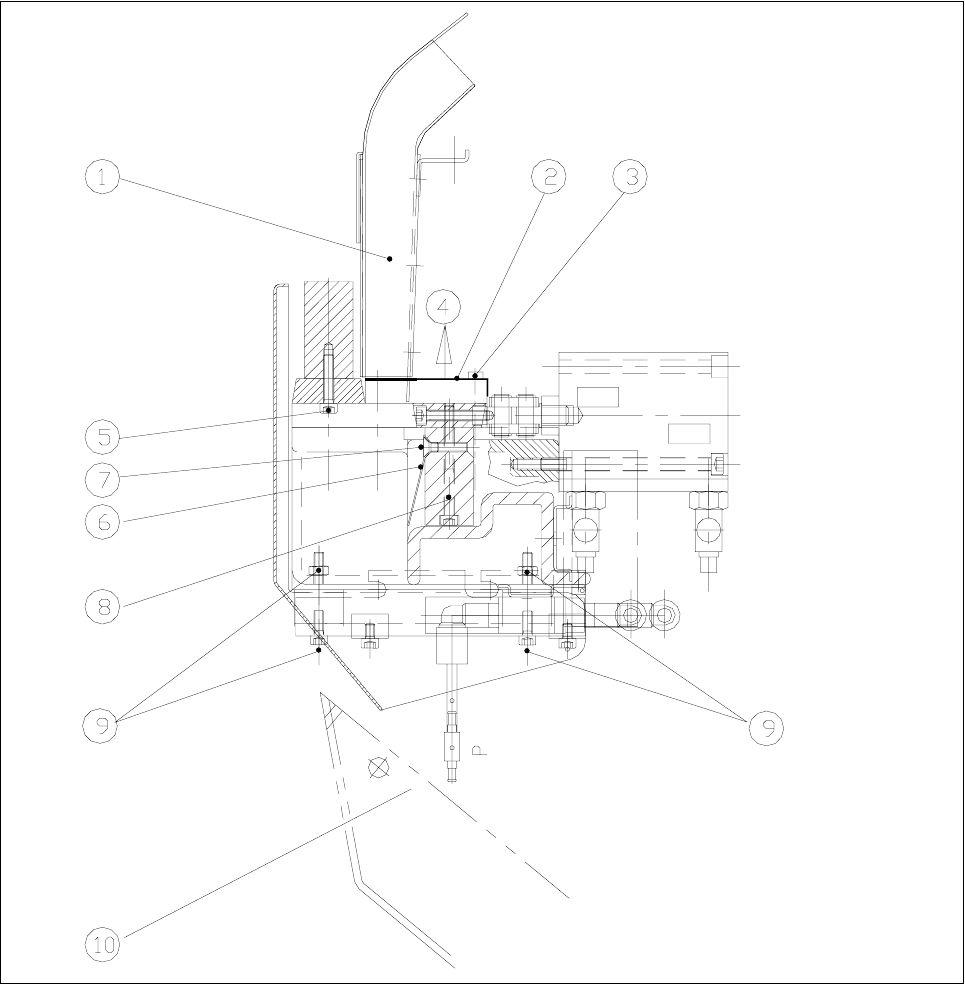
Fig. 14.1.4 Cross Section of Empty-Tape Duct and Pneumatic Cutter
Key:
1) Empty-tape duct 2) Cover plate
3) Fastening of the cover plate (see also Fig. 14.1.5 -> 9): 4) Direction to remove the cover plate
2 Socket hex bolts, M4 x 25
5) Fastening of the rail - stationary blade: 6) Deflector plate
5 Socket hex bolts, M4 x 20
7) Fastening of the deflector plate: 8) Fastening of rail - movable blade:
4 Oval head machine screws, M4 x 6 5 Socket hex bolts, M4 x 45
9) Fastening of the rubber-metal vibration damper (4): 10) Tape waste chute
1 M 6 socket hex bolt for each, with hex nut