F5 SERVICE MAUNAL.pdf - 第228页
7 Components Table SIPLACE 80 S-20/F4 Service Manual 7.5 Communications Unit Edition 03/97 7 - 26 Fig. 7.5.2 Feeder position test er and assignments of the sockets on the connections panel ● If no vol tage or o utput i s…

SIPLACE 80 S-20/F4 Service Manual 7 Components Table
Edition 03/97 7.5 Communications Unit
7 - 25
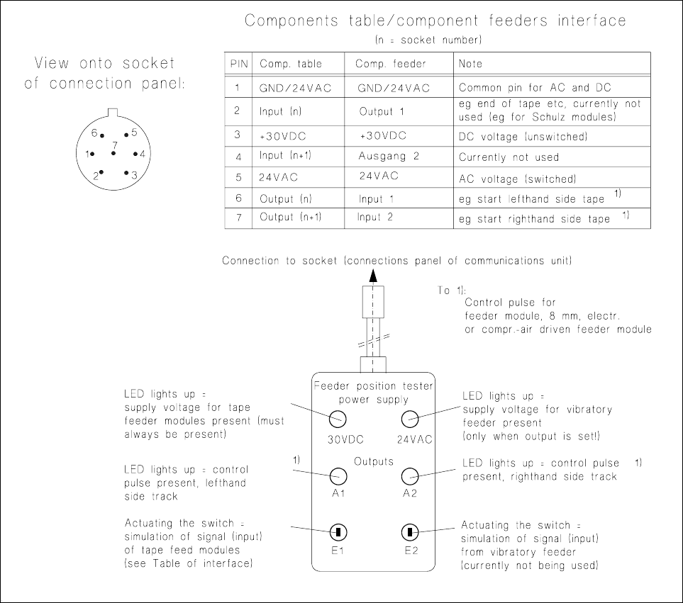
7.5.2.5 Testing the Connection Sockets with the Feeder Position Tester
In the case of error message No. 43 you can carry out the following tests on the individual connection sockets
of the communications unit with the aid of the feeder position tester:
– 30 VDC voltage (always present at the socket),
– a.c. voltage for the vibratory feeders (present only when the conveyor is being operated),
– control pulse (output signal) for tape cycle with tape feeder module 8 mm electrical, V2 (new version),
– control pulse (output signal) for solenoid valve in the compressed air feeder module.
NOTE:
For the purposes of fault location the vibratory feeders can also be activated via the station software:
proceed as follows: pull out the plug of the vibratory feeder → connect up the feeder position tester → menu
"Component feeding" → "Location" →"Vibrate linear feeder" → Return. The output for the vibratory feeders
will remain set until you cancel the function "Vibrate linear feeder" (toggle function).
For further fault location, use the SITEST program. In this case use the feeder position tester as follows:
● Select "Abort placement", quit the placement program and load the SITEST program.
● Testing the +30 VDC voltage for the tape feeder modules:
● Pull out the plugs of the tape feeder modules one after the other from the connections panel, each
time plugging in the feeder position tester (see Fig. 7.5.2):
● The +30 VDC supply voltage must always be present at the socket, and therefore the feeder position
tester LED (see Fig. 7.5.2) must light up each time.
● Testing the a.c. voltage for the vibratory feeders :
● Pull out the plug of one vibratory feeder, connect the feeder position tester to the socket thus freed.
● Set the output for this track by means of the SITEST program by making the following selection:
"Functions" → "Component table" → "Single functions" → "Track" →"Actuate lin. feeder".
The voltage is applied for approx. 200 ms. The corresponding LED on the feeder position tester must
light up briefly (see Fig. 7.5.2), provided the potentiometer under the socket has not been set to "0" →
setting the potentiometer: see the section below.
NOTE:
From SITEST program version 1.64 onwards the duration of vibration is configurable.
● Check all sockets of the connections panel in this way.
● Testing the output (= control pulse) for the module 8 mm electr. and the compressed air feeder module:
● Connect the feeder position tester to the corresponding socket and set the output: "Functions" → "Compo-
nent table" → "Single functions" → "Track" → "Output".
Check the activation of the LED on the feeder position tester for the left-hand and right-hand tracks
(see Fig. 7.5.2).
7 Components Table SIPLACE 80 S-20/F4 Service Manual
7.5 Communications Unit Edition 03/97
7 - 26
Fig. 7.5.2 Feeder position tester and assignments of the sockets on the connections panel
● If no voltage or output is detected during this testing at any one socket or at all of them, replace the com-
munications unit as described in the corresponding section below.
● If voltage and / or the signal are present at the socket, this indicates a fault within the feeder module or in
the connecting cable of the module. Proceed as described for the corresponding feeder module in the Ser-
vice Manual, Section 13.
● With vibratory feeders, before making any fault correction in the module check first the setting of the poten-
tiometer on the connections panel (see Section 7.5.2.6, page 7 - 26).
7.5.2.6 Setting the Vibration Intensity
A precondition for carrying out adjustment is that the basic calibration of the vibratory feeder has already been
carried out and that there are components on the conveyor are.
● Activate the vibrator (vibratory feeder) of the corresponding track:
– With the station software loaded, select:

SIPLACE 80 S-20/F4 Service Manual 7 Components Table
Edition 03/97 7.5 Communications Unit
7 - 27
menu "Component feeding" → "Location" →"Vibrate linear feeder" → Return. The output for the vibra-
tory feeder will remain set until you cancel the function "Vibrate linear feeder" (toggle function).
– With SITEST program version 1.64 loaded, select: "Functions" → "Component table" → "Single func-
tions" → "Track" → "Actuate lin. feeder" → enter the vibration period → Return.
● While the vibration intensity is being activated, turn the corresponding potentiometer rotary button (see
Fig. 7.5.1) until the component is conveyed forward briskly but does not "jump" in the track.
7.5.2.7 Replacing the Communications Unit
● Complete the SITEST program.
DANGER QQQ
Switch off the machine at the main switch and disconnect it from the main power supply.
● Open the protective cover and pull the protective cover at the components feed point upwards and away.
● If necessary, cut the tapes at the front end of the module and pull the remaining tape with components
backwards and out. Roll the tape back onto the reels. The tape reels remain in place in the compartments
as their allocation to the track must be retained.
NOTE:
If you have already unintentionally removed tape reels / feeder modules, restore their original arrange-
ment as described in the User Manual, Section 9 , under "Components tables".
● Pull out all plugs of the feeder modules which are plugged into the connections panel of the communica-
tions unit. The feeder modules will remain in place unchanged.
● Undo the mounting of the front panel of the communications unit (6 recessed head screws M3) and pull the
unit front panel including boards forwards and out a little:
● Undo the plug connections of the cables coming in from the back and
● the screws fastening the housing to the frame (4 socket-head cap screws M4, see Fig. 7.5.1).
● Remove the communications unit out of the frame from the front.
● Install the new communications unit in the reverse sequence of operations. Before refitting the front panel
make sure all plug connections are firmly seated and the back-up battery (see Fig. 7.5.1) is in place.
● Plug all feeder modules into their associated sockets. Insert all tapes into the modules.
● Reconnect the plug connections of the components changeover table in the machine base, connect the
machine to the power supply, switch the machine on.
● Check the activation of the LED for the 24 VAC voltage on the connections panel.
● Check the functioning of the new communications unit using the SITEST program or by component pick-
up from this location. After this, start the placement sequence.