F5 SERVICE MAUNAL.pdf - 第471页
14 Pneumatic Cutter Service Manual SIPLACE 80S- 20/F4/F5 14.1 Pneumatic Cutter and Empty-Tape Duct Edition 04/98 14 - 13 HINWEIS Note the m ountin g posi tions of t he bla des (see Fig . 14.1.6 ). The defle ctor pla te o…
Service Manual SIPLACE 80S-20/F4/F5 14 Pneumatic Cutter
Edition 04/98 14.1 Pneumatic Cutter and Empty-Tape Duct
14 - 12
● In addition, undo the fastening the holddowns (at right and left of the cutter: see Fig. 14.1.5 -> 7, 8).
Remove both holddowns
DQG
the
VSDFHUV
underneath them.
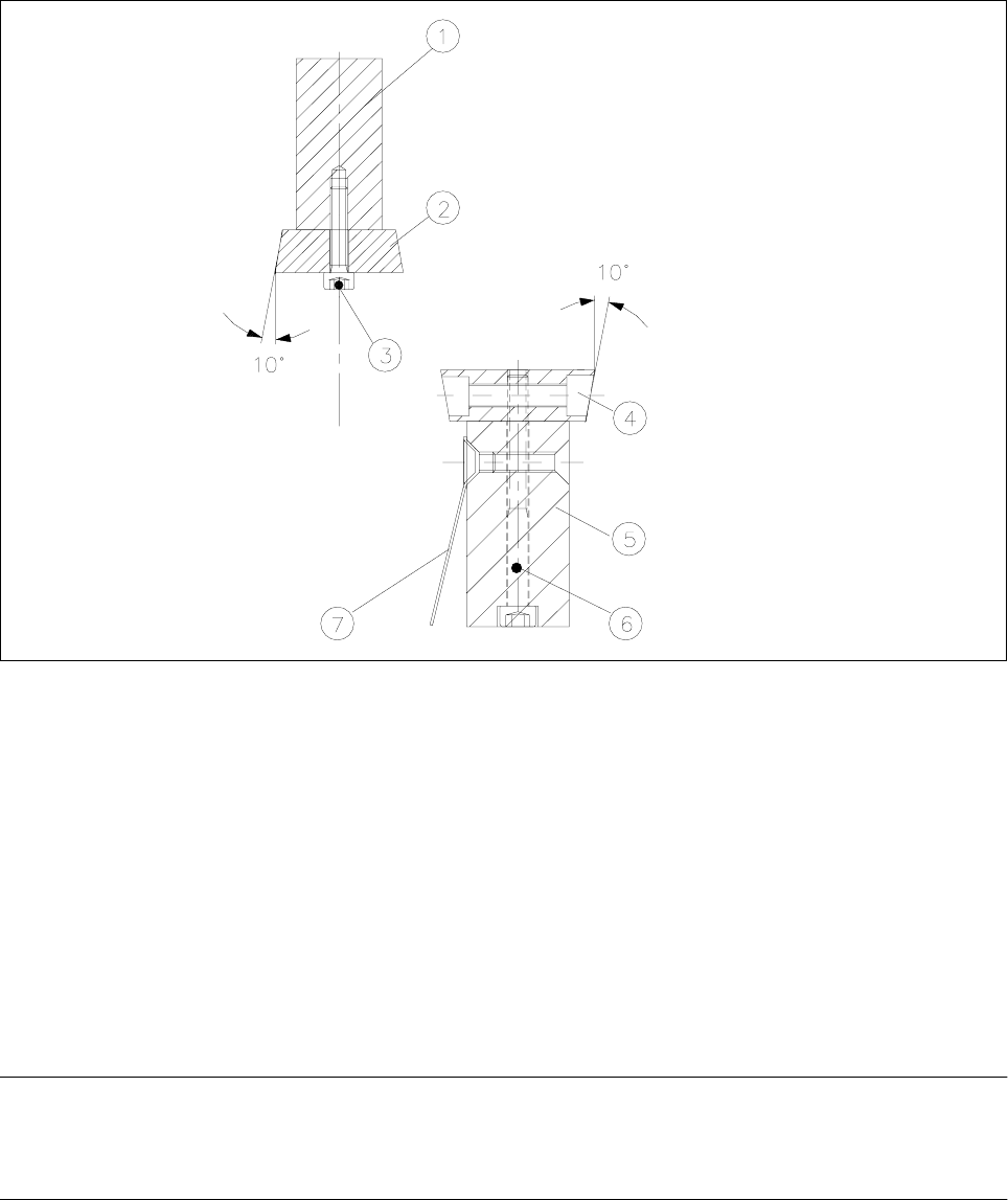
Fig. 14.1.6 Mounting New and Movable Blades; Checking the Mounting position of the Blades
Key:
1) Rail for stationary blade 2) Stationary blade
3) 5 Socket hex bolts, M4 x 20 *) 4) Movable blade
5) Rail for movable blade 6) 5 Socket hex bolts, M4 x 45 *)
7) Deflector plate
*) Loctite no. 243 used on bolts screwed in.
● Dismantle the stationary blade and the movable blade from the rail (see Fig. 14.1.6).
-> The bolts are secured with Loctite no. 243, so considerable strength may be necessary.
● Place a little Loctite no. 243 (item no.: see Section 14.1.3) on the 5 bolts securing each.
WARNING O O
The rotational position of the blades - which can be recognized from the 10° bevel - must be correct (Fig.
14.1.6 and Fig. 14.1.4).
● Bolt the previously removed, FRUUHFWrail onto the QHZPRYDEOHDQGQHZVWDWLRQDU\blade (item nos. of
spare parts: see Section 14.1.2).
● Insert the WZRQHZVSDFHUV (item no.: see Section 14.1.2) into the cutter (see Fig. 14.1.5).

14 Pneumatic Cutter Service Manual SIPLACE 80S-20/F4/F5
14.1 Pneumatic Cutter and Empty-Tape Duct Edition 04/98
14 - 13
HINWEIS
Note the mounting positions of the blades (see Fig. 14.1.6).
The deflector plate on the rail of the movable blade (see Fig. 14.1.6 -> 7) must face the stationary blade (see
Fig. 14.1.6 -> 2).
● ,QVWDOOWKHEODGHVLQFOXGLQJUDLOFRUUHFWO\DQGDVVHPEOHWKHFXWWHU
as described in Section 14.1.7.2.
● Perform the appropriate “Final Steps” (see Section 14.1.17).
14.1.9 Exchanging the Short-Stroke Cylinder Left / Right
The cutter remains installed in the machine.
DANGER O O O
6WULFWO\
adhere to the instructions in the DANGER text in Section 14.1.1.
● Perform all steps up to and including “..loosening the bolts fastening the articulated joint” (in this case only
on the faulty short-stroke cylinder) as described in Section 14.1.7.
-> The movable blade is left
LQVWDOOHG
.
● Mark the mounting position of the disassembled stationary blade (including the rail), e.g., with the water-
insoluble marker:
-> This mounting position ( = right-hand end remains on the right) must be restored during installation.
● Undo the compressed air connections on the faulty short-stroke cylinder (see Fig. 14.1.7 -> 8).
● Loosen the fastening bolts of the two inductive proximity switches on the short-stroke cylinder (one bolt
each: see Fig. 14.1.7 -> 4, 5) and mark the allocation of the proximity switches (position at front/back).
● Loosen bolts fastening the faulty short-stroke cylinder (2 bolts: see Fig. 14.1.7 -> 2) and remove the cylin-
der including the articulated joint which was screwed in.
Service Manual SIPLACE 80S-20/F4/F5 14 Pneumatic Cutter
Edition 04/98 14.1 Pneumatic Cutter and Empty-Tape Duct
14 - 14
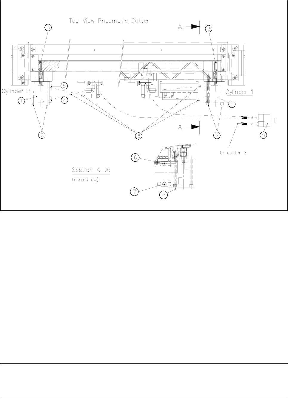
Fig. 14.1.7 Removing and Installing the Short-Stroke Cylinder
.H\
1) Short-stroke cylinders 1 and 2 2) Fastening the short-stroke cylinders
2 socket hex bolts each, M5 x 75
3) Fastening the articulated joint (see also Fig. 14.1.5) 4) Proximity switch (run
LQ
for cylinder)
Fastening: 1 cross-slotted bolt
5) Proximity switch (run
RXW
for position) 6) One-way restrictor (run
RXW
for cylinder)
Fastening: 1 cross-slotted bolt
7) Drosselrückschlagventil (für Zylinder einfahren)
8) Allocation of the compressed air connections, 9) Y-socket union (compressed air 5 bar compressed
air hoses from safety valve)
● Dismantle articulated joint from the cylinder by turning the open-end wrench (width across flats 10) on the
surface indicated in Fig. 14.1.8 -> 3.
NOTE
The threaded pin is secured with Loctite no. 243, so it takes somewhat more strength to loosen it. If neces-
sary, warm the area where it is screwed in until the articulated joint can be loosened.