F5 SERVICE MAUNAL.pdf - 第163页
SIPLACE 80S-20/F4 Service Manual 6 PCB Handling Edition 01/96 6.2 Geared Motors of the PCB Transportation Systems 6 - 7 6.2 Geared Motors of th e PCB T ransp ortation Systems 6.2.1 Replacing the input and ce nter conveyo…
6 PCB Handling SIPLACE 80S-20/F4 Service Manual
6.1 Introduction Edition 01/96
6 - 6
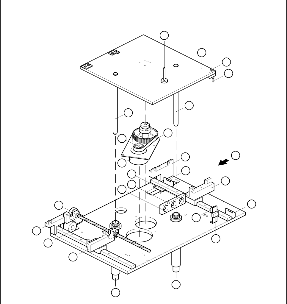
Fig. 6.1.2 Lifting table and width adjustment
1
12
3
4
6
7
5
8
9
10
12
13
14
15
16
17
18
19
20
21
22
4
A
2
11

SIPLACE 80S-20/F4 Service Manual 6 PCB Handling
Edition 01/96 6.2 Geared Motors of the PCB Transportation Systems
6 - 7
6.2 Geared Motors of the PCB Transportation Systems
6.2.1 Replacing the input and center conveyor geared motors
Spare parts, auxiliary materials and equipment
Geared motor with synchronizing disk, Item No. 00324405-01
SITEST program
6.2.1.1 Removing the geared motor from the input and output conveyors
NOTE OOO
You should also comply with the safety instructions given in Chapter 1.
● Select the maximum width setting for the board conveyor so that you can carry out servicing work unim-
peded.
● Move the gantry or gantries to outside the board transportation area.
● Switch off the machine at the main switch and disconnect it from the main power supply.
● Make sure that the machine cannot be switched on while you are carrying out servicing work.
● Mark the installed position of the geared motor and also label the cable connections as protection against
incorrect polarity upon reinstallation.
● Remove the cable shoes from the motor terminals.
● From the conveyor motor strip the heat-shrinkable sleeves which fasten the connecting cable.
● Unscrew and remove the 4 mounting screws (4 M3 slotted head screws) of the geared motor (A).
● Tilt the geared motor a little to one side while carefully pulling the geared motor backwards and out (B).
Make sure that the synchronizing disk does not catch in the toothed belt.
6 PCB Handling SIPLACE 80S-20/F4 Service Manual
6.2 Geared Motors of the PCB Transportation Systems Edition 01/96
6 - 8
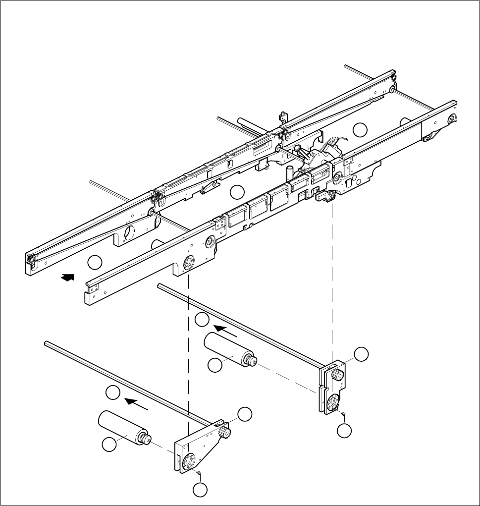
Fig. 6.2.1 Removing the geared motor of the input or center conveyor
Key to Fig. 6.2.1
1 Input conveyor 2 Center conveyor
3 Output conveyor 4 Geared motor
5 Input conveyor motor mount 6 Center conveyor motor mount
3
1
2
4
4
5
6
B
A
A
B