F5 SERVICE MAUNAL.pdf - 第367页
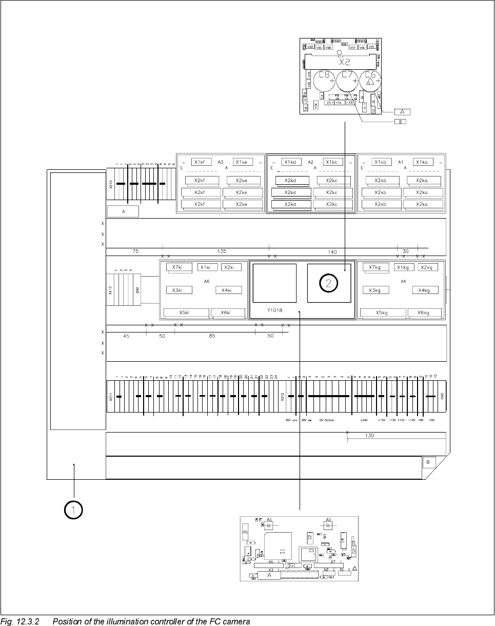
SIPLACE 80S -20/F4/F5 S ervice Man ual 12 Vision systems Edition 09/99 12.4 Replacing the coplanarity laser m odule (SIPLACE 80F) 12 - 15 5HSODFLQ JWKH FRSODQDULW\ ODVHUPRGXO H6,3/$&( ) 6DIHW\L…
SIPLACE 80S-20/F4/F5 Service Manual 12 Vision systems
Edition 09/99 12.4 Replacing the coplanarity laser module (SIPLACE 80F)
12 - 15
5HSODFLQJWKHFRSODQDULW\ODVHUPRGXOH6,3/$&(
)
6DIHW\LQVWUXFWLRQV
DANGER
You must not tamper with or make any modifications of any kind to the safety features or to the coplanarity
laser module ! The laser module must not be operated outside the placement machine and the protective cov-
ers on all sides must be closed.
The coplanarity laser module - when no protec-
tive features are fitted - corresponds to
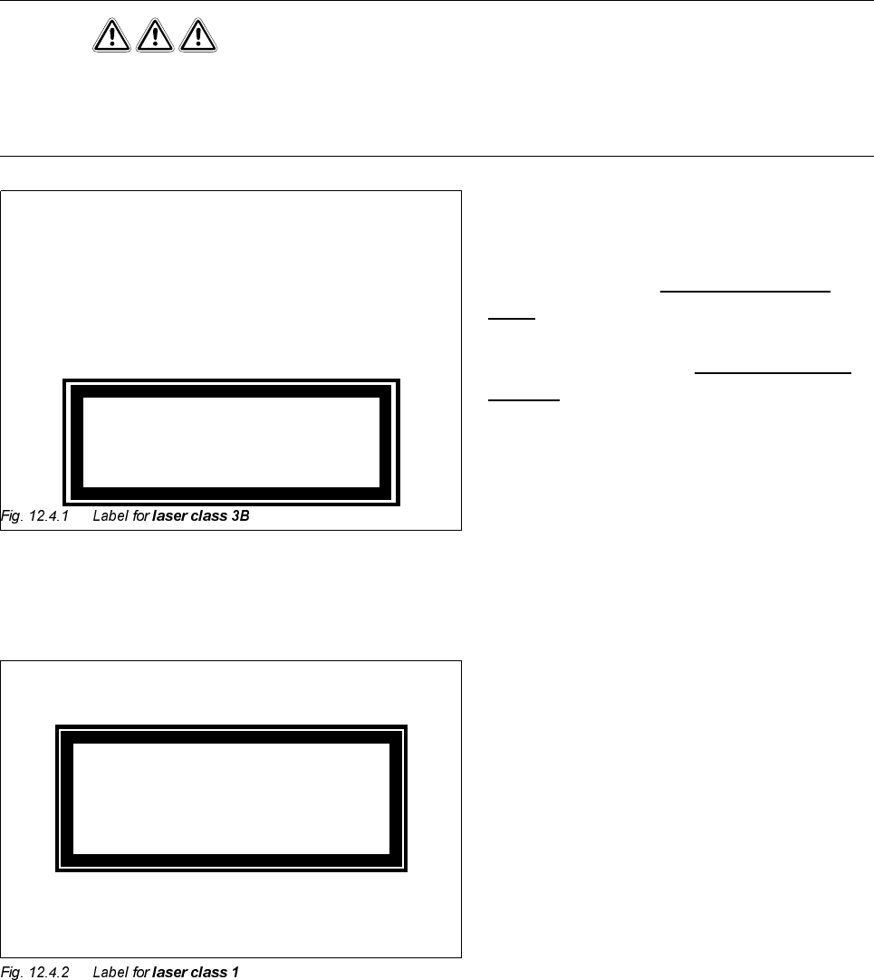
ODVHU
FODVV%
(Fig. 12.4.1)
This means potential
GDQJHUWRH\HVDQG
VNLQ
For this reason the safety features must not be
circumvented or disabled
XQGHUDQ\FLUFXP
VWDQFHV!
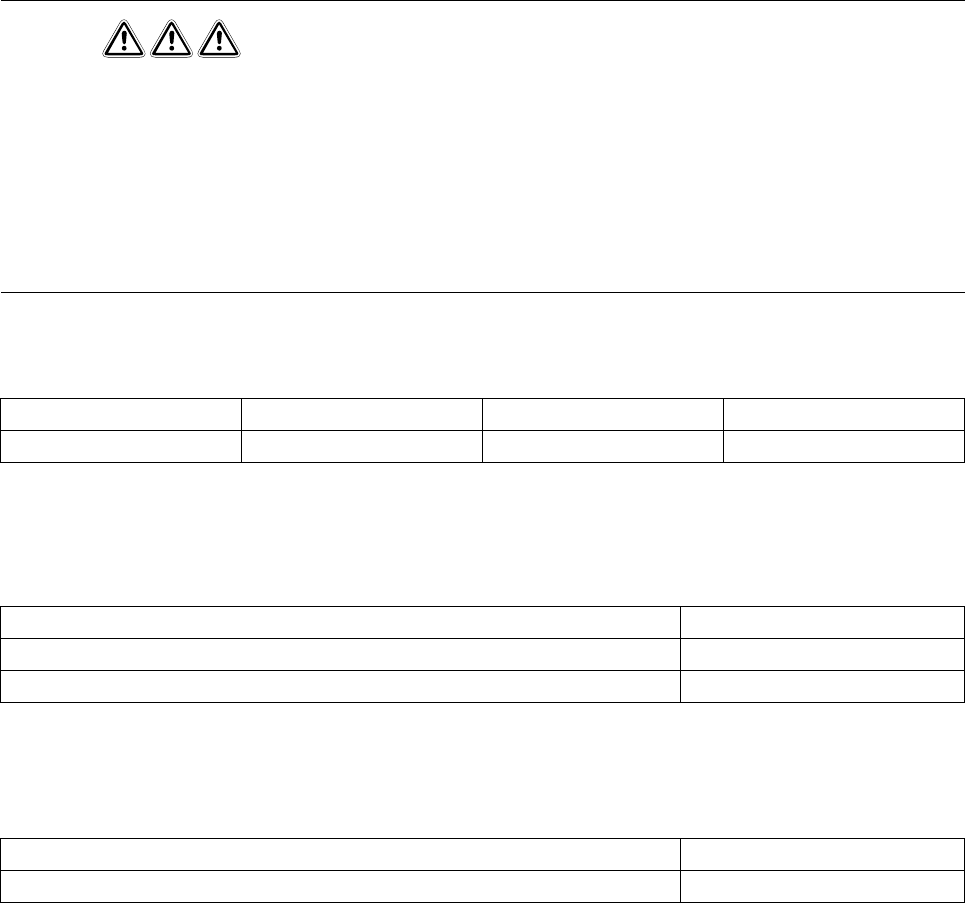
To enable the laser module to be operated in
ODVHUFODVV
with no danger to eyes or skin, the following safety
features have been installed in the machine:
The plug for the power supply (interlock line) is
permanently connected to the machine base.
This means that the laser module can be oper-
ated
RQO\ZKHQLWLVLQVLGHWKHPDFKLQH
The interlock line is connected in series with the
switches for the protective covers. This safety
feature cannot be disabled even by operating
the key-operated switch to bypass the safety
feature. This means that the laser module can
be operatedRQO\ZKHQWKHPDFKLQHLVFORVHG.
K
Invisible laser beam
Do not expose to beam
Laser class 3 B
2.4 mW max., 750 nm; as per IEC 825-1(1993)
Laser class 1
12 Vision systems SIPLACE 80S-20/F4/F5 Service Manual
12.4 Replacing the coplanarity laser module (SIPLACE 80F) Edition 09/99
12 - 16
DANGER
Any unauthorized tampering with or modifications to the equipment will render the factory safety warranty
void !
In addition, the user must comply with the guidelines of the Hauptverband der Berufsgenossenschaften
- VBG 93. In other words:
- Registration with the industrial accident insurance association
- Appointment of a laser safety officer
- Drawing up guidelines for the use of the module
In all other countries the corresponding national guidelines and standards must be complied with:
7RROVLQVSHFWLRQPHDVXULQJDQGWHVWHTXLSPHQWUHTXLUHG
6SDUHSDUWV
5HPRYLQJWKHFRSODQDULW\PRGXOH
● Remove the component changeover table as described in Section 12.1, page 12 - 5.
● Undo the two M4 x 10 hexagon socket screws (see A in Fig. 12.4.3) and lift the coplanarity module up and
away.
,QVWDOOLQJWKHFRSODQDULW\PRGXOH
● Place the coplanarity module in position.
● Slide the 0.5 mm feeler gauge between the module and the support (see B in Fig. 12.4.3).
● Fasten the module back in place using the M4 x 10 hexagon socket screws.
Country Germany Europe International
Standard DIN EN 60825-1/2 EN 60825-1/2 IEC 825-1/2
Set of hexagon socket screwdrivers
Feeler gauge 0.5 mm
SITEST program
'HVLJQDWLRQ )URPLWHPQXPEHU
Coplanarity module SIPLACE 80F 00306397-02