F5 SERVICE MAUNAL.pdf - 第321页
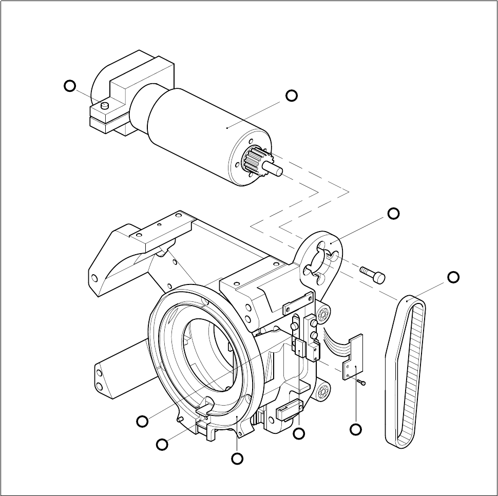
SIPLACE 80S-20/F4 Service Manual 9 12-Segment Revolver Head (10000) Edition 07/97 9.5 Z Axis Unit 9 - 25 Fig. 9.5.1 Z-axis drive and sensor 1 Moto r for z axis 2 Motor m ountin g 3 T oothed belt f or z axis 4 ’Z axis top…

9 12-Segment Revolver Head (10000) SIPLACE 80S-20/F4 Service Manual
9.5 Z Axis Unit Edition 07/97
9 - 24
9.5.5 Replacing the ’Z Axis Bottom’ Sensor
PLEASE NOTE
This work may only be carried out by Siemens service technicians or by the customer’s appropriately trained
personnel.
Spare parts
Sensor ’Z-Axis bottom’, from item no. 00321524S03
Test equipment
Precision test pin, dia. 1.3
, from item no. 00326163-01
● Disconnect plug-in connection X11 from the distributor board.
● Undo the three hexagon socket screws (1 x M2 x 8 and 2 x M2 x 5) of the ribbon cable holders and remove
the ribbon cable.
● Undo the two slotted head screws (M1.6 x 4) and remove the ’Z axis bottom’ sensor.
● Using the precision test pin set the lateral clearance between the light barrier and the nozzle ring to
1.3 mm.
● When re-installing, proceed in the reverse sequence of operations.
NOTE
Be careful when routing the ribbon cable.
SIPLACE 80S-20/F4 Service Manual 9 12-Segment Revolver Head (10000)
Edition 07/97 9.5 Z Axis Unit
9 - 25
Fig. 9.5.1 Z-axis drive and sensor
1 Motor for z axis
2 Motor mounting
3 Toothed belt for z axis
4 ’Z axis top’ sensor
5 Toothed belt fastening
6 Hexagon socket screw
7 Upper stop for z axis
A Insert z-axis gauge here
5
3
A
7
8
4
1
6
2
9 12-Segment Revolver Head (10000) SIPLACE 80S-20/F4 Service Manual
9.5 Z Axis Unit Edition 07/97
9 - 26