F5 SERVICE MAUNAL.pdf - 第438页
13 6-Segment Revolver Head (8000) SIPLACE 80S-20/F4 Service Manual 13.5 Z Axis Unit Edition 07/97 13 - 24 Fig. 13.5.1 Z-axis driv e and sensor 1 Motor fo r z axi s 2 Motor m ountin g 3 T oothed belt for z axis 4 ’Z axis …

SIPLACE 80S-20/F4 Service Manual 13 6-Segment Revolver Head (8000)
Edition 07/97 13.5 Z Axis Unit
13 - 23
13.5.5 Replacing the ’Z Axis at Bottom’ Sensor
PLEASE NOTE
This work may only be carried out by Siemens service technicians or by the customer’s appropriately trained
personnel.
Spare parts
Sensor ’Z-axis at bottom’, from item no. 00321524S03
Test equipment
Precision test pin, dia. 1.3
, from item no. 00326163-01
● Disconnect plug-in connection X11 from the distributor board.
● Undo the three hexagon socket screws (1 x M2 x 8 and 2 x M2 x 5) of the ribbon cable holders and remove
the ribbon cable.
● Undo the two slotted head screws (M1.6 x 4) and remove the ’Z axis at bottom’ sensor.
● Using the precision test pin set the lateral clearance between the light barrier and the nozzle ring to
1.3 mm.
● When re-installing, proceed in the reverse sequence of operations.
NOTE
Be careful when routing the ribbon cable.
13 6-Segment Revolver Head (8000) SIPLACE 80S-20/F4 Service Manual
13.5 Z Axis Unit Edition 07/97
13 - 24
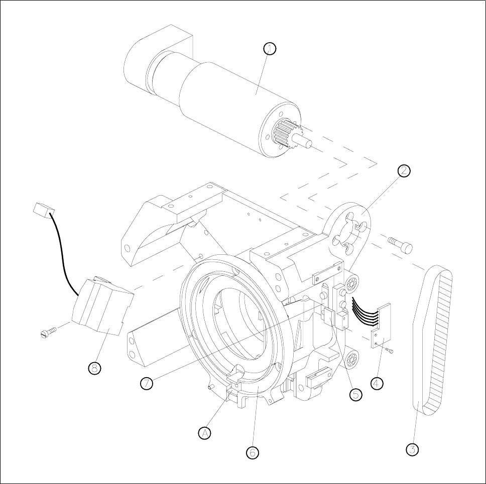
Fig. 13.5.1 Z-axis drive and sensor
1 Motor for z axis
2 Motor mounting
3 Toothed belt for z axis
4 ’Z axis at top’ sensor
5 Toothed belt fastening
6 Clamping ring
7 Upper stop for z axis
8 D-axis encoder
A Insert z-axis gauge here

SIPLACE 80S-20/F4 Service Manual 13 6-Segment Revolver Head (8000)
Edition 07/97 13.6 Star Complete
13 - 25
13.6 Star Complete
13.6.1 Removing the ’Star Complete’
PLEASE NOTE
This work may only be carried out by Siemens service technicians or by the customer’s appropriately trained
personnel.
Spare parts
Star, mounted, from item no. 00324957S01
NOTE
When working on the star hold the front part of the head horizontally.
By marking the star and the motor shaft make sure you can refit the star into its original position.
● Remove the front part of the placement head (see section 13.1.6).
● Remove all sleeves.
● Undo the three hexagon socket screws (M3 x 8) in the front part of the star (see Fig. 13.6.1).
● Now lift the complete star assembly until the ball bearings of the segments are exposed.
● Now pull all segments outwards and pull the star completely away.
ATTENTION ∆
!
∆
!
Make sure you not to damage any of the vacuum lines when you remove the star.
13.6.2 Fitting the ’Star Complete’
● Pull all segment guides to the outside.
● Place the star carefully on the motor shaft. Watch out for the three mounting locations.
● Now make sure that no vacuum hoses are jammed between the star and the motor shaft.
● Slide all segment guides back in place. Make sure that all ball bearings of the segments run in the arced
segments guide.
● Press the star lightly onto the motor shaft and fasten it with the three hexagon socket screws (M3 x 8).