F5 SERVICE MAUNAL.pdf - 第372页
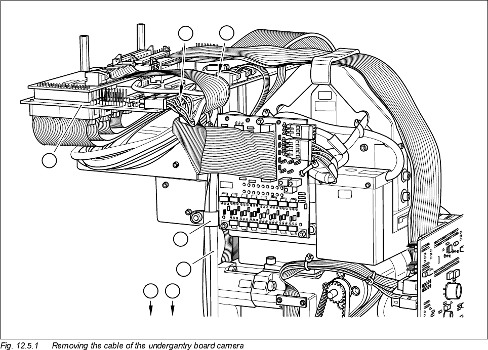
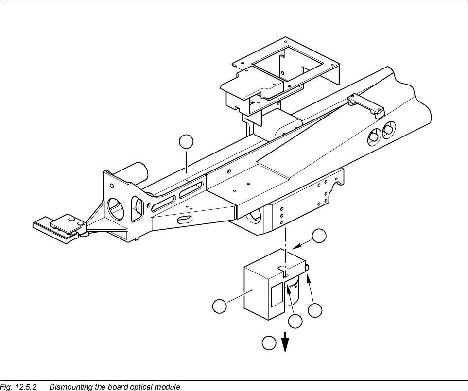
12 Vision s ystems SIPLA CE 80S-20/F4/F5 Service Manual 12.5 Replacing the undergantry P CB cam era Edition 09/99 12 - 20 Key to Fig. 1 2.5.2 1 Gantr y 2 Boar d underga ntry ca mera A Undo the M2 x 10 m ountin g screw B …
SIPLACE 80S-20/F4/F5 Service Manual 12 Vision systems
Edition 09/99 12.5 Replacing the undergantry PCB camera
12 - 19
Key to Fig. 12.5.1
,QVWDOOLQJWKHERDUGXQGHUJDQWU\FDPHUD
● When fitting, proceed in the reverse sequence of actions Section 12.5.3, page 12 - 18.
● Check once more the correct seating of the plug and cable.
6HWWLQJZRUN
● Calibrate the board undergantry camera with the aid of the SITEST program.
● Replace the feeder modules which you removed. Make sure they are fitted to the components table in the
correct order.
1 Conversion board ’small axis C0005’
2 Undergantry PCB camera cable
A Cable clips
B Connecting the board camera cable to the conversion board C0005
0240
0025
0025
0240
0240
1
A
B
A
2
AA

SIPLACE 80S-20/F4/F5 Service Manual 12 Vision systems
Edition 09/99 12.6 Coplanarity Option
12 - 21
12.6 Coplanarity Option
6DIHW\,QVWUXFWLRQV
DANGER O O O
Only Siemens service engineers or service engineers of the customer who have been trained at Siemens are
permitted to perform the servicing described here.
There must be assurance that the customer’s service engineer will also receive instruction from the laser pro-
tection officer. Only Siemens service engineers or the customer’s Siemens-trained service engineers are per-
mitted to put the machine back into service initially after the coplanarity option has been serviced.
During all work, conform to the safety instructions in Chapter 1 of this Service Manual. which take prece-
dence. During all work inside the machine base in particular you must comply with the more stringent safety
regulations in DIN EN 60204.
The machines in the SIPLACE family are powered with 3 x 400 V +/- 10%, 50/60 Hz mains voltage.
Portions of the system therefore carry dangerous voltage. Some assemblies inside the machine base do so
even when the main switch is off.
Improper handling of the machine or contact with portions thereof which are live may result in death or serious
bodily injury as well as extensive property damage. Before beginning any service work, turn the machine off at
the main switch and pull out the mains plug.
Before dismantling or assembling the old cutter (with rotating blade) or the new cutter (with stationary and
movable cutter strips) the compressed air feed on the main valve of the compressed air unit in the machine
base must also be shut off and the air bled from the compressed air lines by actuating the vent plug.
To prevent the machine from being reactivated without authority, secure it as described in Chapter 1 of the
User Manual under "Locking the Machine...").
The component table and the cutter are very heavy, a 2nd strong person is therefore required when they are
being disassembled (risk of being crushed).
There is always a high risk of injury from the blades of the cutter (risk of being cut!).
For this reason, you should follow all SAFETY INSTRUCTIONS in the pertinent SIPLACE Service Manual
when disassembling and assembling the cutter (see instructions in Section 12.6.2).
Never put your hand into the cutter from below or into the empty-tape duct from above.
In particular, when removing or installing the "pneumatic cutter" grasp it only from above and from the outside
left and right becausem when disassembled, the blade is exposed (unprotected) at the bottom. Never
set the disassembled pneumatic cutter on a part of your body (e.g., on your knees or thighs) and never put
your feet under the cutter. If you were to do so, you would inure yourself severely or at least damage your
clothes.
Also make certain that no one can injur themselves on the disassembled cutter which you have placed next
to the machine. The best procedure is to put it in an appropriate package (container) for the time being.