F5 SERVICE MAUNAL.pdf - 第224页
7 Components Table SIPLACE 80 S-20/F4 Service Manual 7.5 Communications Unit Edition 03/97 7 - 22 DANGER QQQ Switch o ff the machi ne at the ma in swi tch and d isconne ct it from the ma in power supply . ● Pull o ut the…

SIPLACE 80 S-20/F4 Service Manual 7 Components Table
Edition 03/97 7.5 Communications Unit
7 - 21
7.5 Communications Unit
7.5.1 Tools and Spare Parts Required
Tools
● Crosstip screwdriver, size 1
Auxiliary Measuring and Test Equipment
● Feeder position tester, from item no. 00304770-03
● Ohmmeter
Spare Parts
● Back-up battery (battery, lithium), from item no. 00314295-03
● Communications unit complete, from item no. 00116013-04
● Control signals - components table cable, Y559-W1, from item no. 00300380-06
● Miniature fuse 5x20/T3, 16A / glass, from item no. 00304938-04
7.5.2 Fault Location and Correction
NOTE
With error Nos. 43 and 400 there could be a defect within the communications unit; with error No. 399 ("Pro-
gram loss of table and trolley control") it may be that only back-up battery of the processor board needs
replacing.
Start fault location by consulting the section Section 7.2 ’Fault Characteristics’.
The circuit diagrams for the communications unit ("Components table processor board" and "Components
table controller board") will be found in the current circuit diagrams folder.
If there is a defect in one of the boards then the complete communications unit will always be replaced.
7.5.2.1 Replacing the Back-Up Battery
With the error message "Program loss of table and trolley control" proceed as follows:
● Try to load the table once more. Select from within the "Machine errors menu" the menu item "Load table
program" → Return.
● If the error message "Program loss of table and trolley control" appears again, select "Abort placement" so
that all of the components picked-up at the placement heads in the course of the following reference run
can be returned. The placement heads travel to the stand-by position above the components loading point
in question (location 1 or location 3).
7 Components Table SIPLACE 80 S-20/F4 Service Manual
7.5 Communications Unit Edition 03/97
7 - 22
DANGER QQQ
Switch off the machine at the main switch and disconnect it from the main power supply.
● Pull out the plug X37 on the right-hand side of the machine base and also the power plug of the compo-
nents changeover table in question.
● Disconnect all plug connections of the modules at the connections panel of the communications unit:
The tapes must remain in position!
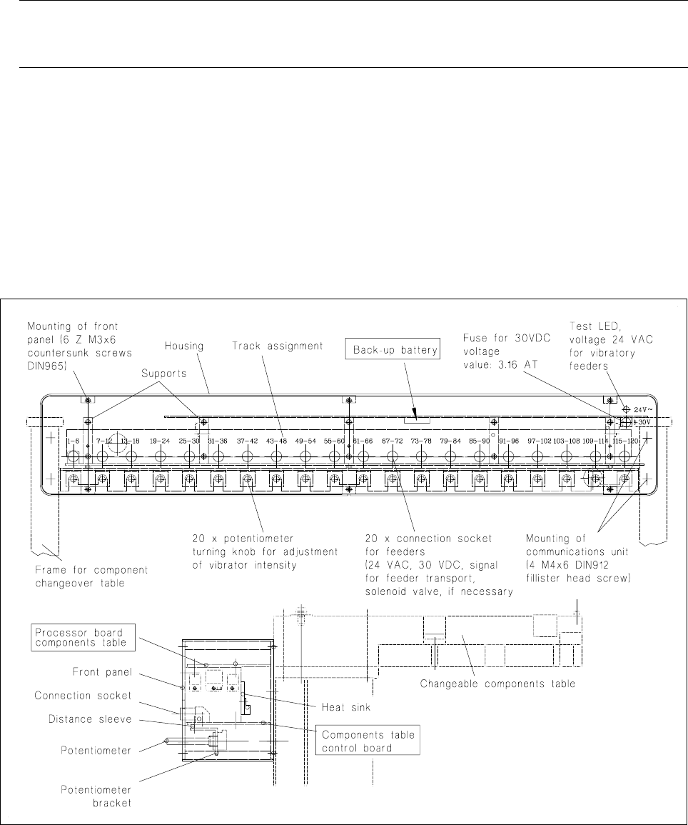
● Remove the front panel of the communications unit (6 recessed head screws M3).
● The back-up battery is located on the underside of the processor board = top board (see Fig. 7.5.1):
Slide the back-up battery forwards and out of its holder and slide in the new battery making sure the polar-
ity is correct: minus-pole points upwards! (see marking on the holder).
Fig. 7.5.1 Structure of the communications unit, replacement of the back-up battery
Refit the front panel and plug the feeder modules back into their connection sockets in the communications
unit.
● Reconnect the components changeover table back to plugs X37 and to the mains plug.
● Switch on the machine and start placement sequence. The components table will be loaded automatically
at the new start: in other words, the table program will be loaded into the memory of the components table
controller.
SIPLACE 80 S-20/F4 Service Manual 7 Components Table
Edition 03/97 7.5 Communications Unit
7 - 23
7.5.2.2 Checking and Replacing Fuse F1
The error message "Communication with table interrupted" may point to the fuse F1 being defective.
● Select "Abort placement". The picked-up components will be returned.
● Switch off the machine at the main switch.
● Unscrew and remove the fuse F1 which is to be found on the right-hand side of the connections panel (see
Fig. 7.5.1):
– The fuse has blown:
● First correct the cause of this:
– Short circuit in the feeder module: check this, for example, by connecting to the external power
supply.
– Short circuit within the empty tape cutting device: See Section 7.6.2.1 ’Checking the + 30 V Elec-
tric Circuit : Fuse, Plug Connections, Motor Activation, Solenoid Valve’
● Replace accordingly the fuse F1: 3.16 AT.
● First make sure the plug connections of the components changeover table at the machine base (X37 and
mains plug) are seated firmly.
● Switch the machine on and start the placement sequence.
– The fuse has not blown: proceed as described in the next section.
7.5.2.3 Locating an Interruption in Cable Y559-W1 and the Communications Unit
● The machine was already switched off during fault location work (see above).
● Pull out the plug X37 (Components table interface cable Y559-W1) on the right of the machine base.
● Remove the front panel of the communications unit (6 recessed head screws M3).
● Pull the boards (= one unit) a little towards you and disconnect the plug connection of the components
table interface cable Y559-W1 which enters the unit through a cable penetration at the back.
● In the following inspection refer to the circuit diagram 1710460-Y0559-...-L-. (circuit diagrams folder):
Check the cable Y559-W1 for breaks using an ohmmeter (acoustical signal upon if there is continuity):
– Cable break: replace the cable Y559-W1 as described in the section below.
– No break: proceed as described below:
● For test purposes install a new communications unit (see Section 7.5.2.7 ’Replacing the Communications
Unit’).
● Connect up the components changeover table on the right-hand side of the machine base (X37, mains
plug, and if applicable pneumatics connection).
● Slide in the side cover, if applicable, and close the guard; switch the machine on.