F5 SERVICE MAUNAL.pdf - 第267页
SIPLACE 80S-20/F4 Service Manual 8 IC Head Edition 01/97 8.2 Structure and Functional Groups of t he IC Head 8 - 5 Key to Fig. 8.2.1 =D[LV The z ax is consis ts of the f ollowing princi pal componen ts: – Servo m …
8 IC Head SIPLACE 80S-20/F4 Service Manual
8.2 Structure and Functional Groups of the IC Head Edition 01/97
8 - 4
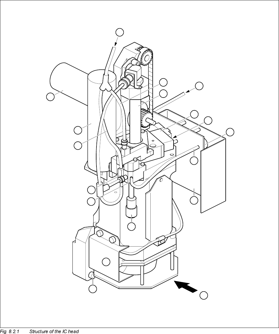
6WUXFWXUHDQG)XQFWLRQDO*URXSVRIWKH,&+HDG
1
2
3
A
5
7
6
8
B
9
10
11
12
13
14
15
16
4
SIPLACE 80S-20/F4 Service Manual 8 IC Head
Edition 01/97 8.2 Structure and Functional Groups of the IC Head
8 - 5
Key to Fig. 8.2.1
=D[LV
The z axis consists of the following principal components:
– Servo motor, tachogenerator and incremental encoder
– Synchroflex toothed belt
– Sleeve and
– End position BERO
The servo motor moves the sleeve in the vertical direction by means of the Synchroflex toothed belt. The res-
olution of the incremental position measurement is 27.7 digits per millimeter travel.The end position BERO
signals the upper sleeve position.
During the approach to the reference point, the z axis moves up to the upper stop, changes direction,
searches for the zero pulse and then moves to the 0 digit position by the amount indicated by the zero point
correction. The gantry axes must not start to move until
– the z axis is in the 0 digit position and
– the end position BERO has been activated.
'U$[LV
The dr axis consists of the following principal components:
– Servo motor with tachogenerator
– Pair of friction wheels
– Incremental encoder
The angular resolution of the dr axis is 72,000 digits per 360°, i.e. 1 digit corresponds to 1/200°.
1 Compressed air supply for vacuum generation 2 Sleeve (z axis)
3 2.3 ± 0.2 bar for opening the z axis clamping device 4 Solenoid valve for z axis clamping device
5 Vacuum sensor 6 Lead for vacuum sensor
7 IC head C0006 conversion board 8 Silencer
9 Fixing screw for IC head 10 Encoder for dr axis
11 Vacuum generator 12 ’Forced air’ solenoid valve
13 ’Forced air’ compressed air supply 14 Servo motor for dr axis
15 Servo motor for z axis
A Manual actuation of solenoid valve for
z axis clamping device
B Viewed in IC head mounting direction
8 IC Head SIPLACE 80S-20/F4 Service Manual
8.2 Structure and Functional Groups of the IC Head Edition 01/97
8 - 6
3QHXPDWLF6\VWHP
The pneumatic system supplies the placement head with the compressed air it requires and generates the
necessary vacuum. The pneumatic system is made up of the following assemblies:
– Vacuum generator
– Forced air supply
– Z axis clamping device
– Vacuum measurement board
9DFXXP*HQHUDWRU
A nozzle on the vacuum generator creates the vacuum required. The input pressure is 5.6 bar. The noise
level is reduced by a silencer downstream of the vacuum generator. A solenoid valve above the vacuum gen-
erator switches the forced air on and off. The vacuum is switched on as soon as the z axis is set down on the
component so that it can be picked up. The vacuum generator is switched off and forced air is fed into the
nozzle in order to insert the component.
)RUFHG$LU
The forced air separates the component from the nozzle during insertion and discarding. The lower solenoid
valve on the vacuum generator switches the forced air on and off. The two solenoid valves above and below
the vacuum generator for switching the vacuum or the forced air on and off work alternately.
=$[LV&ODPSLQJ'HYLFH
The z axis clamping device performs two important tasks:
– It clamps the z axis in its upper end position in order to prevent the sleeve dropping out when the machine
is switched off or the z axis is deactivated. This will also prevent a manual head crash.
– For the coplanarity measurement in the automatic placement system, the z axis must be absolutely sta-
tionary. This is only possible with the z axis clamping device. The measurement is taken as follows:
● Activate the z axis clamping device
● Disable the z axis
● Take the coplanarity measurement
● Activate the z axis
● Deactivate the z axis clamping device
At rest, the z axis clamping device is always active. It cannot be deactivated by the solenoid valve until the
compressed air supply has reached working pressure. If the pressure of the compressed air supply to the z
axis clamping device is significantly below the working pressure of 2.3 bar, the z axis will be clamped. The
z axis clamping device is not deactivated until the axis is moved.