F5 SERVICE MAUNAL.pdf - 第330页
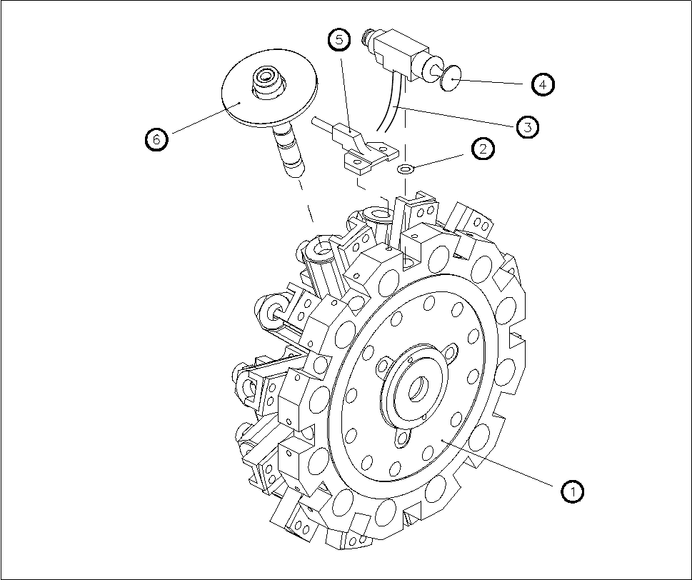
9 12-Segment Revolver Head (10000) SIPLACE 80S-20/F4 Service Manual 9.7 Replacing the Valve for Vacuu m / Forced Air an d Hose Edition 07/97 9 - 34 Fig. 9.7.1 V ac uum / forced air valve and hose 1 Star comp lete 2O - r …

SIPLACE 80S-20/F4 Service Manual 9 12-Segment Revolver Head (10000)
Edition 07/97 9.7 Replacing the Valve for Vacuum / Forced Air and Hose
9 - 33
9.7 Replacing the Valve for Vacuum / Forced Air and
Hose
PLEASE NOTE
This work may only be carried out by Siemens service technicians or by the customer’s appropriately trained
personnel.
Spare parts
SP6-12 valve, from item no. 00319774S02
Plastic hose, silicone, 1.5 x 3.5, natural, from item no. 00323387S01
● Remove the front part of the placement head (see section 9.1.7).
● Remove the star complete (see section 9.6.1).
● Carefully remove the vacuum hose from the segment guide.
● Undo the two slotted head screws (M1.5 x 4) and remove the valve block (see Fig. 9.7.1).
● Watch out for the o-ring located in the base of the star.
● When re-installing the valve and vacuum hose proceed in the reverse sequence of operations.
● To fit the star complete, see section 9.6.2. To record the star axis zero point correction, see section 9.6.3.
ATTENTION ∆
!
∆
!
When fitting the valve block look out for the cutaway in the valve block and the o-ring in the star base. The cut-
away serves as a guide for the valve block.
NOTE
The vacuum hose must be cut precisely to length. Make sure it fits onto the segment guide without twisting.
ATTENTION ∆
!
∆
!
The vacuum hose must not rub against the adjacent vacuum hoses.
9 12-Segment Revolver Head (10000) SIPLACE 80S-20/F4 Service Manual
9.7 Replacing the Valve for Vacuum / Forced Air and Hose Edition 07/97
9 - 34
Fig. 9.7.1 Vacuum / forced air valve and hose
1 Star complete
2O-ring
3Hose
4 Valve block
5 Forced air supply
6Sleeve

SIPLACE 80S-20/F4 Service Manual 9 12-Segment Revolver Head (10000)
Edition 07/97 9.8 Replacing the Star Brake
9 - 35
9.8 Replacing the Star Brake
9.8.1 Tools and Test Equipment
Hexagon socket screw keys, set
SITEST program
Adjustment instructions
9.8.2 Spare Parts
Brake for star, complete, from item no. 00328781-01
9.8.3 Replacing the Brake
● Remove the front part of the placement head (see Section 9.1.7, Page 9 - 8).
● Undo the two M1.6x5 hexagon socket screws (see pos. A of Fig. 9.8.1).
● Replace the brake and fix the brake in place using the hexagon socket screw - do not tighten up the screw
yet.
● Using your forefinger press the brake lightly against the two hexagon socket screws (see pos. B of Fig.
9.8.1). The brake is now correctly positioned.
● Tighten up both hexagon socket screws.
● Reinstall the front part of the placement head (see Section 9.1.6, Page 9 - 7).
NOTE
When you remove or re-install the front part of the placement head note that the star is rotated by 15° out of its
zero position (vertical sleeve position).
When you fit the front part of the placement head, make sure that the distributor disc (see pos. 3, Fig. 9.4.2,
Page 9 - 19) is positioned correctly.