F5 SERVICE MAUNAL.pdf - 第179页
SIPLACE 80S-20/F4 Service Manual 6 PCB Handling Edition 01/96 6.4 Conveyor Toothed B elts 6 - 23 ● Carry ou t the fol lowing wo rk on the mova ble side of the b oard con veyor: – On th e insi de unsc rew and r emove the …
6 PCB Handling SIPLACE 80S-20/F4 Service Manual
6.4 Conveyor Toothed Belts Edition 01/96
6 - 22
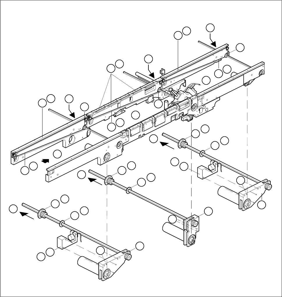
Fig. 6.4.2 Removing the conveyor toothed belt on the movable side of the board conveyor
Key to Fig. 6.4.2
● Remove the cable shoes from the motor terminals.
● Remove the heat-shrinkable sleeve rings which attach the cable to the geared motor.
1 Input conveyor 2 Center conveyor
3 Output conveyor 4 Guide rails
5 Sonar BERO mount 6 Drive unit of the input and output conveyors
7 Center conveyor drive unit 8 Conveyor toothed belt
9 Disk 10 Flange
C
10
9
D
C
10
9
D
C
10
9
D
3
1
2
6
5
B
5
B
6
7
E
E
F
E
F
F
4
A
4
A
4
A
8
G
8
G
8
G
9
9
9
10
10
10

SIPLACE 80S-20/F4 Service Manual 6 PCB Handling
Edition 01/96 6.4 Conveyor Toothed Belts
6 - 23
● Carry out the following work on the movable side of the board conveyor:
– On the inside unscrew and remove the two M 2 x 5 slotted head screws of the disk on the hexagonal
shaft (C).
– On the outside unscrew and remove the three M 3 x 5 hexagon socket screws in the flange (D).
● Undo and remove the two M4 hexagon socket screws which fasten the drive unit to the side part of the
fixed side of the board conveyor (E).
● Slide the drive unit in the direction of the movable conveyor side until the synchronizing disk of the drive
and the conveyor toothed belt on the fixed side of the conveyor belt no longer engage with one another (F).
● Support the drive unit so that the hexagonal shaft does not get bent.
● Remove the conveyor toothed belt from the guide channel of the movable side of the conveyor and lift it
over the drive unit and away (G).
● Insert the new toothed belt.
● Fit the drive unit, sonar BERO (except with the center conveyor) and the guide rail.
6.4.2.2 Function Test
● Carry out a function test of the conveyor as specified in the adjustment instructions.
NOTE OOO
With the function test do not fail to comply with the safety instructions in Chapter 1.
● Unlock the key-operated switch before performing function testing and making adjustments. This will allow
you to take measurements at the motors with the protective cover open. However the gantry axis systems
will be in a de-energized state.
NOTE O
When you have finished the function test do not forget to lock the key-operated switch again, stowing the
key in a place where unauthorized persons have no access to it.
6 PCB Handling SIPLACE 80S-20/F4 Service Manual
6.4 Conveyor Toothed Belts Edition 01/96
6 - 24