F5 SERVICE MAUNAL.pdf - 第139页
SIPLACE 80S -20/F4/F4-6/F5 Service Manual 5 Gantries Edition 09/99 5.7 Exchanging the X-/Y-Trailing Cable 5 - 31 Fig. 5.7.7 Putting Connectors Side by Side and Wrapping Them wit h Masking Tape ● Prepa re the ribb on cab …
5 Gantries SIPLACE 80S-20/F4/F4-6/F5 Service Manual
5.7 Exchanging the X-/Y-Trailing Cable Edition 09/99
5 - 30
5.7.6.2 Y-Gantry Area: Preparing Ribbon Cable Package for Removal
WARNING O O
During the following steps in the area of the gantry board, comply with regulations on ESDs (see Section 1 of
this service manual).
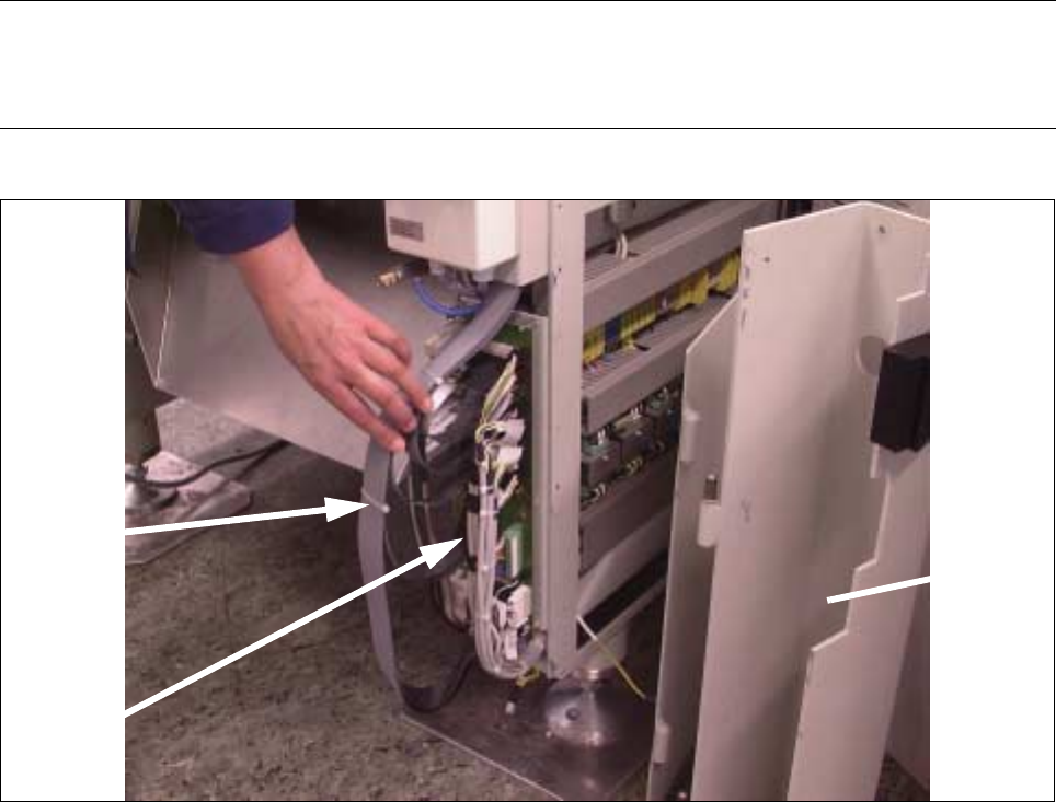
Fig. 5.7.6 Removing Ribbon Cable Ties, Disconnecting Plug-In Connections on the board
● Carefully remove the ties on the ribbon cable package (see Fig. 5.7.6 -> 1).
● Disconnect the plug-in connectors of the ribbon cable coming from the trailing cable (see Fig. 5.7.6 ->
2). The markings on the board and the cables define the allocations.
3 cable
ties
Gantry
board
Side guard
(dismantled)
SIPLACE 80S-20/F4/F4-6/F5 Service Manual 5 Gantries
Edition 09/99 5.7 Exchanging the X-/Y-Trailing Cable
5 - 31
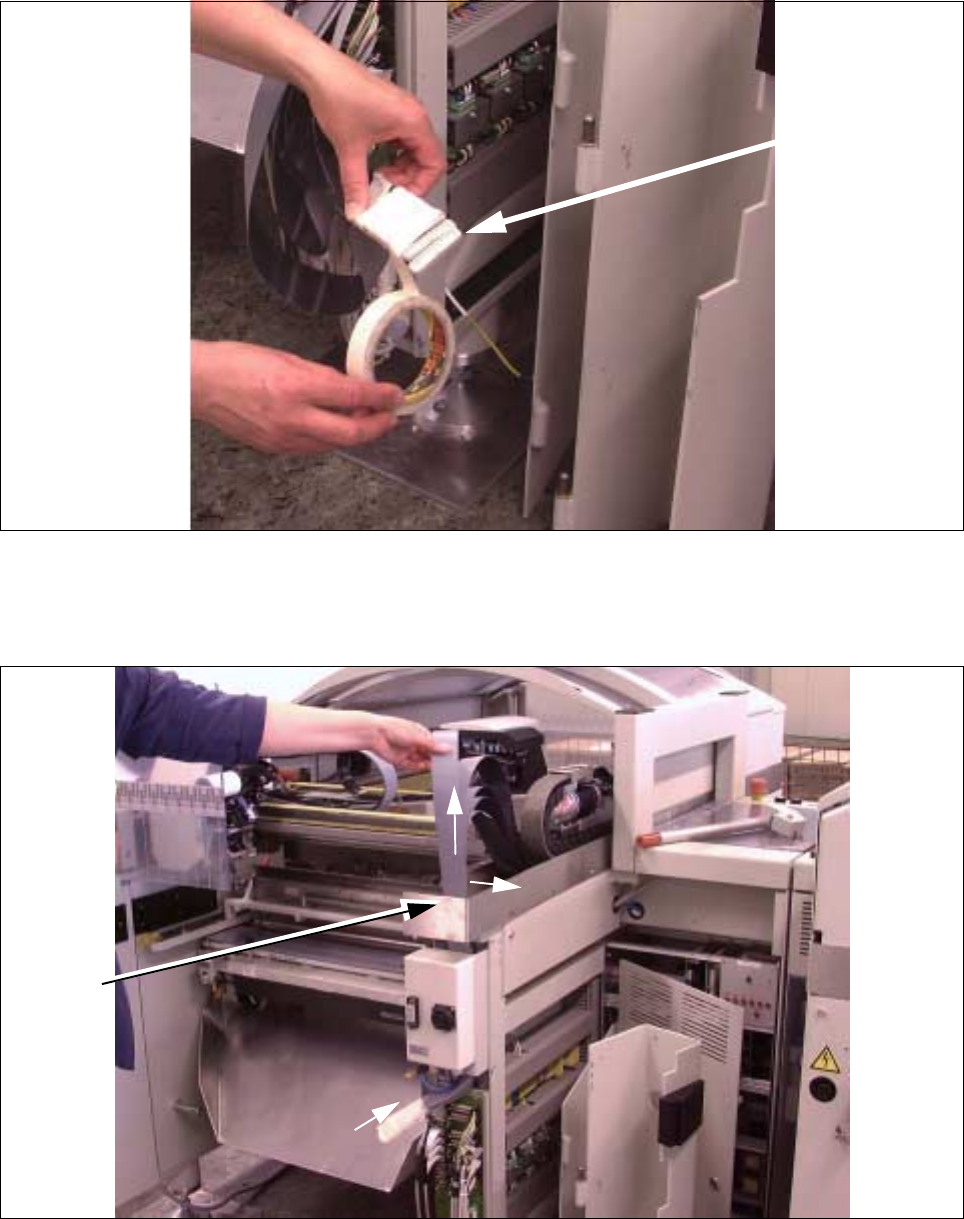
Fig. 5.7.7 Putting Connectors Side by Side and Wrapping Them with Masking Tape
● Prepare the ribbon cables for disassembly as shown:
Place the ribbon cables precisely side-by-side and wrap them with Masking tape.
Fig. 5.7.8 Unhooking Ribbon Cable Package on Cable Hanger and Pulling It Up and Out
● First pull the entire ribbon cable package up sideways out of the cable hanger and the top and then care-
fully and completely out the top as shown in Fig. 5.7.8 (Pos. 1, 2).
Ribbon cable
connection
(side-by-side)
2
2
1
Cable
hanger
5 Gantries SIPLACE 80S-20/F4/F4-6/F5 Service Manual
5.7 Exchanging the X-/Y-Trailing Cable Edition 09/99
5 - 32
5.7.6.3 Y-Gantry Area: Loosening the Pneumatic Hoses
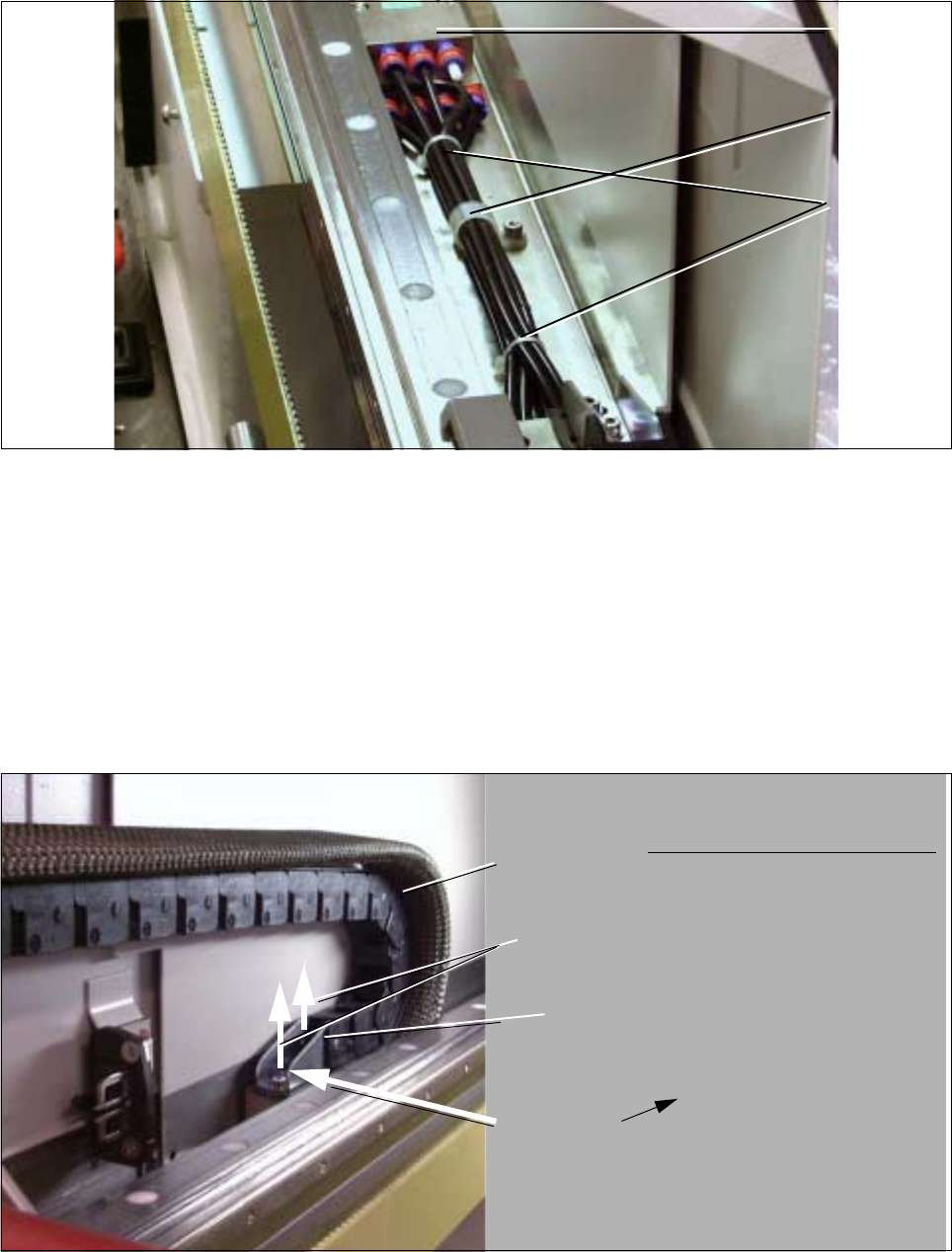
Fig. 5.7.9 Loosening Connections on the Pneumatic Block and Hose Clamps
● Loosen all the ties and hose clamps on the hose package (M3 screw: see Fig. 5.7.9). On the S20: 1 cable
clamp, 2 hose clamps; On F4 / F5: 2 cable clamps and 4 hose ties.
● Loosen all pneumatic connections on the air distributor block (see Fig. 5.7.9).
This is accomplished by pushing the red ring in the direction of the block.
5.7.6.4 Y-Gantry Area: Loosening the Pneumatic Hoses
Fig. 5.7.10 Loosening the Screws Fastening the Cable Supply Chain; Removing the Y-Strain Relief Device under It
(Example S-20, Gantry 2)
Air
distributor
block
Hose clamp
Cable ties
Cable supply
Two M 4 screws
U-bracket
Y-strain relief
chain
device
Top View: Y-Strain Relief Device