F5 SERVICE MAUNAL.pdf - 第174页
6 PCB Handling SIPLACE 80S-20/F4 Service Manual 6.3 Drive Units of the PCB Transportation Systems E dition 01/96 6 - 18 6.3.3 Replacing the output conv eyor drive unit Spare parts, auxili ary materials and equipment Driv…
SIPLACE 80S-20/F4 Service Manual 6 PCB Handling
Edition 01/96 6.3 Drive Units of the PCB Transportation Systems
6 - 17
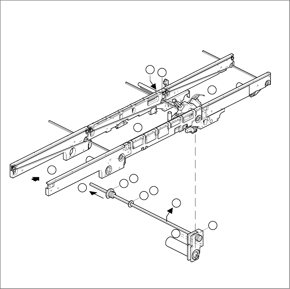
Fig. 6.3.2 Removing the drive unit of the center conveyor
3
1
2
6
8
7
B
8
7
C
D
F
E

6 PCB Handling SIPLACE 80S-20/F4 Service Manual
6.3 Drive Units of the PCB Transportation Systems Edition 01/96
6 - 18
6.3.3 Replacing the output conveyor drive unit
Spare parts, auxiliary materials and equipment
Drive unit, transfer conveyor, fixed right-hand, Item No. 00324315-01
SITEST program
6.3.3.1 Removing and installing the output conveyor drive unit
NOTE OOO
You should also comply with the safety instructions in Chapter 1 and Section 6.3.1.1, Page 6 - 13.
Removal and installation are described in Section 6.3.1.1, Page 6 - 13 and Section 6.3.1.2, Page 6 - 15.
NOTE
Move the movable side of the board conveyor and stop it 10 cm before the maximum width setting. This will
leave you enough room to remove the flange on the movable side of the conveyor.

SIPLACE 80S-20/F4 Service Manual 6 PCB Handling
Edition 01/96 6.4 Conveyor Toothed Belts
6 - 19
6.4 Conveyor Toothed Belts
6.4.1 Replacing the conveyor toothed belt on the fixed side of the
board conveyor
NOTE
These instructions apply to all three board conveyors.
Spare parts, auxiliary materials and equipment
Synchroflex toothed belt, Item No. 00200196-01
SITEST program
6.4.1.1 Changing the conveyor toothed belt on the fixed side of the board conveyor
NOTE OOO
You should also comply with the safety instructions in Chapter 1.
● Select the maximum width setting for the board conveyor so that you can carry out servicing work unim-
peded.
● Move the gantry or gantries to outside the board transportation area.
● Switch off the machine at the main switch and disconnect it from the main power supply.
● Make sure that the machine cannot be switched on while you are carrying out servicing work.
● Slacken off the M3 hexagon socket screws which fasten the guide rails to the fixed side of the conveyor in
question (A).
● Undo the two M4 hexagon socket screws which fasten the drive unit in question to the side panel (B).
● Slide the drive unit in the direction of the movable conveyor side until the synchronizing disks of the drive
and of the conveyor toothed belt no longer engage with one another (C).
● Support the drive unit so that the hexagonal shaft does not get bent and remove the conveyor belt from the
side panel (D).
● Insert the new toothed belt into the side panel.
● Fit the drive unit and the guide rails back onto the side panel.