F5 SERVICE MAUNAL.pdf - 第146页
5 Gantries SIPLACE 80S-20/F4/F4-6/F5 Service Manual 5.7 Exchanging the X -/Y-Trailing Cable Edition 09/99 5 - 38 l Removing the entir e trailing cable: ● Remove the ent ire ribbon cabl e packag e and th e 7-tube p neumat…
SIPLACE 80S-20/F4/F4-6/F5 Service Manual 5 Gantries
Edition 09/99 5.7 Exchanging the X-/Y-Trailing Cable
5 - 37
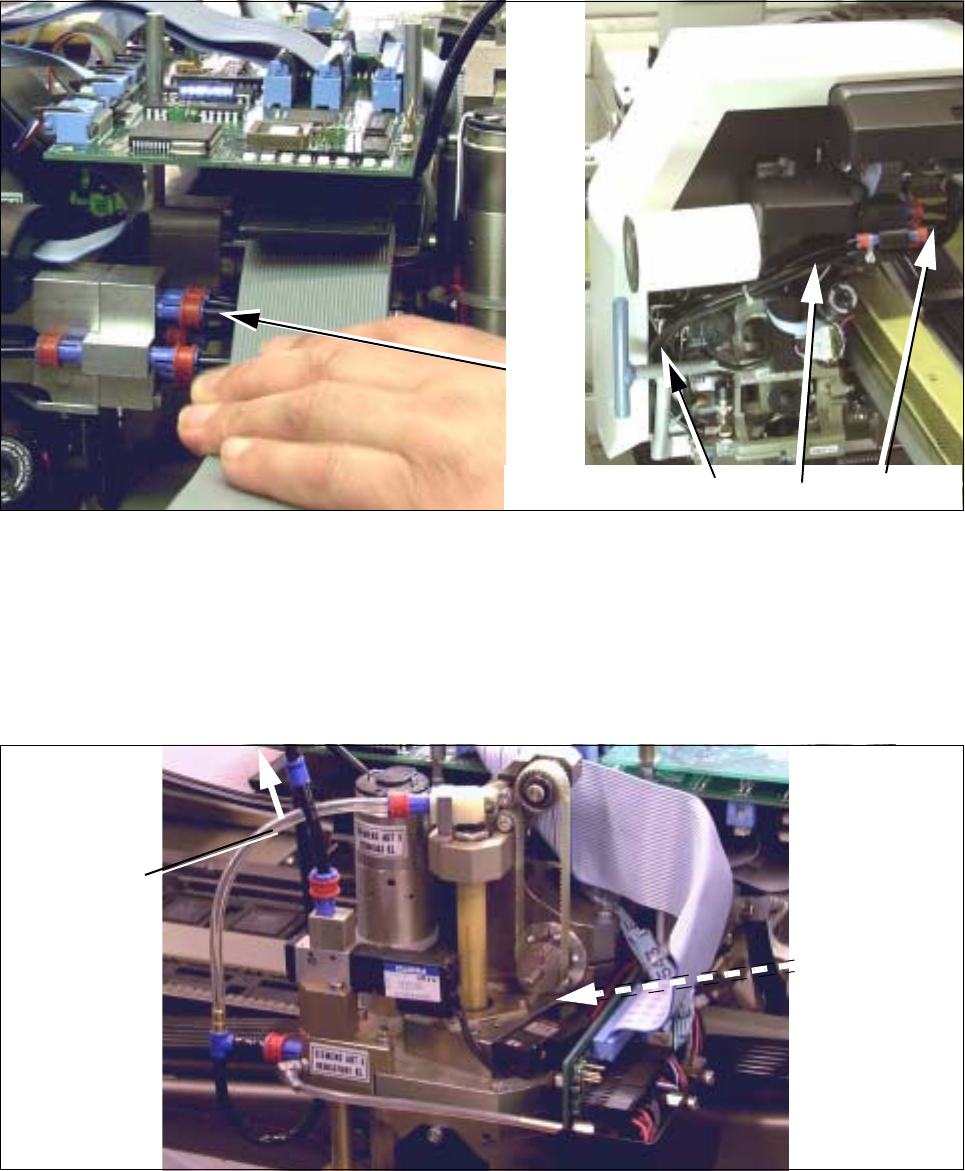
● Loosening the pneumatic connections in the placement head area:
Fig. 5.7.16 S-20 and F4/F5: Loosening Pneumatic Connections on the Revolver Head (or Reconnecting and Laying Them Correctly)
● S-20 and F5/F5: Loosen the 5 compressed air connections on the distributor block of the revolver
head (move red ring of quick-release fastener: see Fig. 5.7.16 -> 1).
On S-20, hoses 1 and 2 are not under pressure. For this reason they are run down the side of the
revolver head (see top right -> 2) and inserted behind the cross member (-> 3).
Loosen the 2 cable ties.
Fig. 5.7.17 F4/F5: Loosening the Pneumatic Connections on the IC Head (or Reconnecting Them Correctly)
● F4/F5: In addition to the connections on the revolver head (see Fig. 5.7.17), loosen the compressed
air connections on the IC head:
- 5.5 bar on the vacuum generator (Y-coupling: see Fig. 5.7.17) and
- 2.3 bar at solenoid valve for the Z-axis clamping unit (quick-release fastener: see Fig. 5.7.17).
1
F4 / F5
3
2
1
S-20
1
S-20
Connection to
pneumatic
system
2,3 bar
Connection to
pneumatic
vacuum
5,5 bar
system for
generator
(Y-connector)
for Z-axis
clamping unit

5 Gantries SIPLACE 80S-20/F4/F4-6/F5 Service Manual
5.7 Exchanging the X-/Y-Trailing Cable Edition 09/99
5 - 38
l Removing the entire trailing cable:
● Remove the entire ribbon cable package and the 7-tube pneumatic hose from the machine.
NOTE
If a single ribbon cable is faulty, all of the cables are removed because a complete, new set will be installed.
5.7.7 Installation
5.7.7.1 Installing New Protective Hose (without Exchanging the Cables/Hoses)
CAUTION O
A polyester hose is always used on machine option F5 DCA instead of the standard protective hose (see
Section 5.7.2).
If you are exchanging only the protective hose, proceed as follows:
● Place the separated hose ends (Y-gantry area, air distributor) flat side-by-side and wrap them with
Masking tape.
● Push the ribbon cable and pneumatic hoses carefully into the new protective hose, wrapped end first.
● Push the protective hose into the correct position relative to the Y-trailing cable hanger. Use the pressure
imprints on the existing pneumatic hose for orientation.
● Connect the hoses to the air distributor block next to the Y-gantry rail. Hoses No. 1 and 2 must be cor-
rectly assigned. To ensure this, refer to Fig. 5.7.18 and the relevant diagram of the pneumatic system (S-
20 and/or F4 / F5) from the current file of electric circuit diagrams
● Run the Y-trailing cable and fasten the protective hose to the Y-trailing cable hanger as described in Sec-
tion 5.7.7.5.

SIPLACE 80S-20/F4/F4-6/F5 Service Manual 5 Gantries
Edition 09/99 5.7 Exchanging the X-/Y-Trailing Cable
5 - 39
5.7.7.2 X-Gantry Area: Installing New Ribbon Cables and Pneumatic Hoses
Starting from the placement head, connect and run the cables and hoses exactly. This will enable you to
accommodate the resultant remaining length of the ribbon cable package behind the side guard.
Comply with the NOTE in Section 5.7.5.
● If you install a new, 7-tube pneumatic hose (Item No.: see Section 5.7.2), first perform the following
steps:
● Separate the hoses for the connection in the placement head area only at the upper end at first as
executed at the old hose.
● Using the disassembled 7-tube hose as a model, cut the separated new hoses for the head area in
appropriate lengths and at right angles.
To allocate the lengths, refer to the hose numbers (if imprinted) on the hoses. If the numbers for
tubes 1 to 7 are missing, at least mark No. 1 in the end areas of the tubes as specified in Fig. 5.7.18
(e.g., with labeled insulating tape, etc.).
Fig. 5.7.18 S-20 and F4/F5: Overview: Correctly Inserting and Connecting the 7-Tube Pneumatic Hose