F5 SERVICE MAUNAL.pdf - 第439页
SIPLACE 80S-20/F4 Service Manual 13 6-Segment Revolver Head (8000) Edition 07/97 13.6 Star Complete 13 - 25 13.6 Star Complete 13.6.1 Removing the ’Star Complete’ PLEASE NOT E This wor k may o nly be c arried out by Siem…
13 6-Segment Revolver Head (8000) SIPLACE 80S-20/F4 Service Manual
13.5 Z Axis Unit Edition 07/97
13 - 24
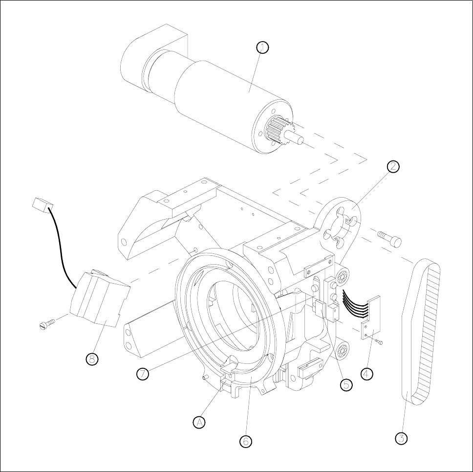
Fig. 13.5.1 Z-axis drive and sensor
1 Motor for z axis
2 Motor mounting
3 Toothed belt for z axis
4 ’Z axis at top’ sensor
5 Toothed belt fastening
6 Clamping ring
7 Upper stop for z axis
8 D-axis encoder
A Insert z-axis gauge here

SIPLACE 80S-20/F4 Service Manual 13 6-Segment Revolver Head (8000)
Edition 07/97 13.6 Star Complete
13 - 25
13.6 Star Complete
13.6.1 Removing the ’Star Complete’
PLEASE NOTE
This work may only be carried out by Siemens service technicians or by the customer’s appropriately trained
personnel.
Spare parts
Star, mounted, from item no. 00324957S01
NOTE
When working on the star hold the front part of the head horizontally.
By marking the star and the motor shaft make sure you can refit the star into its original position.
● Remove the front part of the placement head (see section 13.1.6).
● Remove all sleeves.
● Undo the three hexagon socket screws (M3 x 8) in the front part of the star (see Fig. 13.6.1).
● Now lift the complete star assembly until the ball bearings of the segments are exposed.
● Now pull all segments outwards and pull the star completely away.
ATTENTION ∆
!
∆
!
Make sure you not to damage any of the vacuum lines when you remove the star.
13.6.2 Fitting the ’Star Complete’
● Pull all segment guides to the outside.
● Place the star carefully on the motor shaft. Watch out for the three mounting locations.
● Now make sure that no vacuum hoses are jammed between the star and the motor shaft.
● Slide all segment guides back in place. Make sure that all ball bearings of the segments run in the arced
segments guide.
● Press the star lightly onto the motor shaft and fasten it with the three hexagon socket screws (M3 x 8).

13 6-Segment Revolver Head (8000) SIPLACE 80S-20/F4 Service Manual
13.6 Star Complete Edition 07/97
13 - 26
ATTENTION ∆
!
∆
!
You must be very careful when carrying out this work as otherwise you could pinch or tear away a vacuum
hose.
● Re-insert the vacuum distributor disk (see section 13.4.4).
● Now place the vacuum distributor onto the star with the flat sides facing each other. Pay attention to the
two guide pins.
– Please refer to the adjustment instructions for information on checking the electrical functions.
– Please refer to the Sitest instructions for information on adjusting the entire placement head.
13.6.3 Recording the Zero Point Correction for the Revolver Head Star
Axis
Test equipment
Gauge for star, from item no. 00326164-01
● Load the Sitest program.
● Sitest menu → Axes → Star axis → Modify axis data → Positions → Zero point correction.
● Type 0 into the zero point correction line and carry out a reference run with the axis.
● Disable the star axis and turn the star clockwise until sleeve no. 1 is in the placement position.
● Remove sleeve no. 1.
● Screw the gauge for the star onto the placement head housing.
● Insert the pin through the fork of the gauge for the star and into the segment guide (insert the chamfered
pin end first).
● Sitest menu → Axes → Star axis → Read actual position.
● Press the star axis lightly by hand to the right. Read and make a note of the actual position.
● Now press the star axis lightly by hand to the left. Once again read off and make a note of the actual posi-
tion.
● Calculate the average of the two values you have noted (X1 + X2) / 2.
● Pull the pin out of the segment guide and remove the zero point gauge. Now replace the segment and
switch on the star axis.
● Sitest menu → Axes → Star axis → Modify axis data → Positions → Zero point correction.
● Type in the new zero point correction value.
● Sitest menu → Store MA file → AXMA.DAT.
NOTE
Carry out a reference run with the star axis and check the zero point correction with the zero point gauge.
The deviations from the first and second values should be about the same in the positive and negative direc-
tions of rotation.