F5 SERVICE MAUNAL.pdf - 第172页
6 PCB Handling SIPLACE 80S-20/F4 Service Manual 6.3 Drive Units of the PCB Transportation Systems E dition 01/96 6 - 16 6.3.2 Replacing the drive unit of the center conveyor Spare parts, auxili ary materials and equipmen…

SIPLACE 80S-20/F4 Service Manual 6 PCB Handling
Edition 01/96 6.3 Drive Units of the PCB Transportation Systems
6 - 15
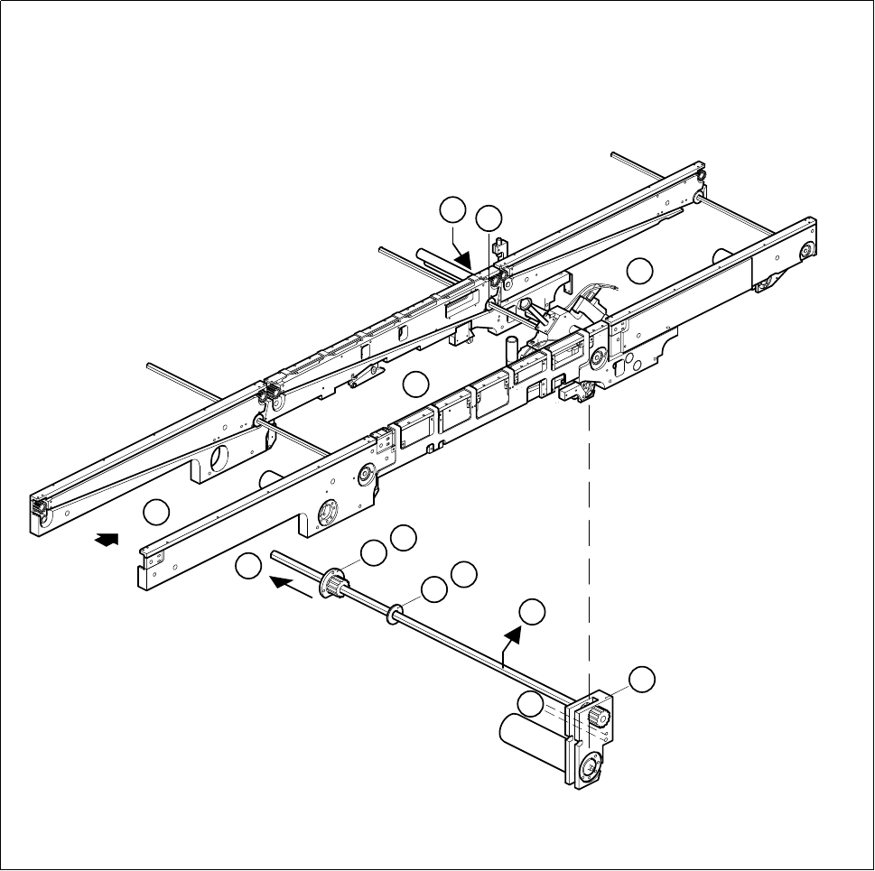
6.3.1.2 Fitting and testing the input and output conveyor drive units
● First of all, slide the synchronizing disk onto the hexagonal shaft. Make sure that the disk is correctly posi-
tioned on account of the countersunk holes.
● Slide the flange with the synchronizing disk onto the hexagonal shaft.
● Mount the drive unit on the fixed side of the conveyor.
● Mount the disk and the flange on the movable side of the conveyor.
● Plug the cable shoes onto the terminals of the geared motor and refer to the circuit diagram folder to make
sure that you have connected the motor up correctly.
● Slide the heat-shrinkable sleeve rings onto the motor to fasten the motor cable.
● Fit the sonar BERO mount.
● Referring to the adjustment instructions, carry out a function test of the conveyor.
NOTE OOO
While carrying out the function test do not fail to observe the safety instructions in Chapter 1.
● Unlock the key-operated switch before performing function testing and making adjustments. This will allow
you to take measurements at the motors with the protective cover open. However the gantry axis systems
will be in a de-energized state.
NOTE O
When you have finished the function test do not forget to lock the key-operated switch again, stowing the
key in a place where unauthorized persons have no access to it.

6 PCB Handling SIPLACE 80S-20/F4 Service Manual
6.3 Drive Units of the PCB Transportation Systems Edition 01/96
6 - 16
6.3.2 Replacing the drive unit of the center conveyor
Spare parts, auxiliary materials and equipment
Drive unit, center conveyor, fixed right-hand, Item No. 00324314-01
SITEST program
6.3.2.1 Removing the center conveyor drive unit
NOTE OOO
You should comply with the safety notes in Chapter 1 and in Section 6.3.1.1, Page 6 - 13.
Remove the drive unit as described in Section 6.3.1.1, Page 6 - 13 for the input conveyor. Note that item (A)
’Removing the sonar BERO mount’ does not apply.
NOTE
If a nozzle changer for the turret head is installed in the movable side of the conveyor you should remove it
first.
6.3.2.2 Fitting the center conveyor drive unit
Installation of the drive unit is described in Section 6.3.1.2, Page 6 - 15.
NOTE
Once you have re-installed the nozzle changer you will need to carry out measurement work again.
SIPLACE 80S-20/F4 Service Manual 6 PCB Handling
Edition 01/96 6.3 Drive Units of the PCB Transportation Systems
6 - 17
Fig. 6.3.2 Removing the drive unit of the center conveyor
3
1
2
6
8
7
B
8
7
C
D
F
E