F5 SERVICE MAUNAL.pdf - 第364页
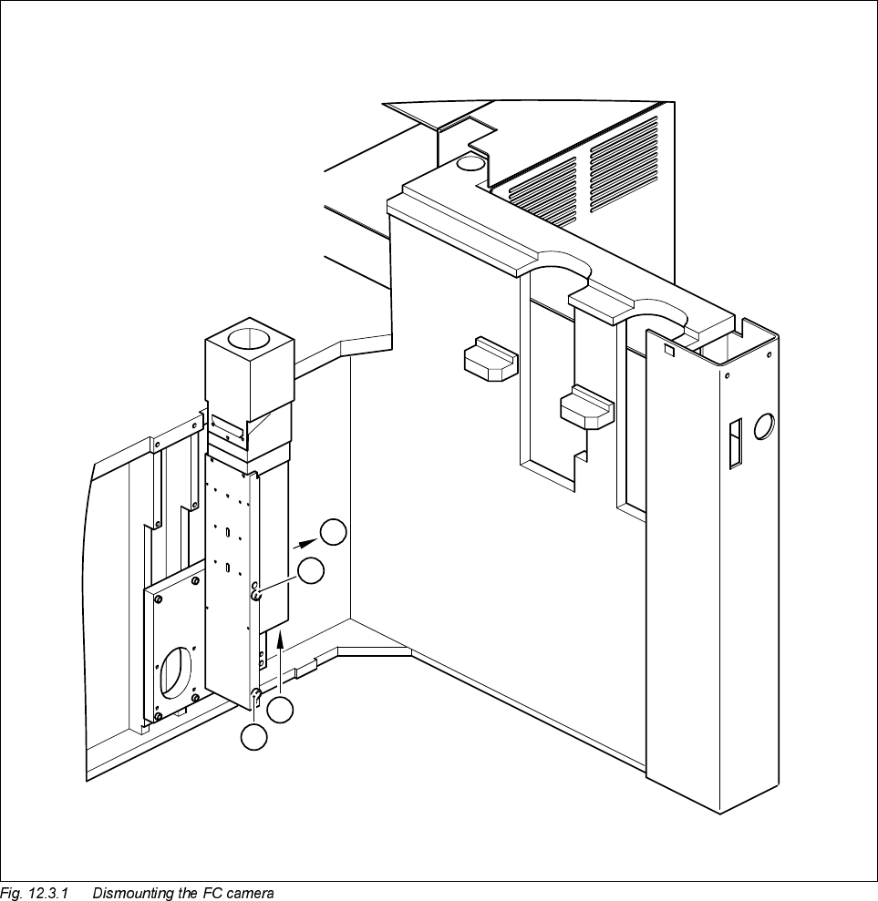
12 Vision s ystems SIPLA CE 80S-20/F4/F5 Service Manual 12.3 Replacing the flip-chip vision camera and illumination controller (SIPLACE 80F) Edition 09/99 12 - 12 Key to Fig. 1 2.3.1 A Remove th e cover B Unplug the plug…

SIPLACE 80S-20/F4/F5 Service Manual 12 Vision systems
Edition 09/99 12.3 Replacing the flip-chip vision camera and illumination controller (SIPLACE 80F)
12 - 11
5HSODFLQJWKHIOLSFKLSYLVLRQFDPHUDDQG
LOOXPLQDWLRQ FRQWUROOHU 6,3/$&()
NOTE
Make sure that you always replace the flip-chip vision camera and the illumination control board Y1019 as a
pair since the two components are adjusted to each other. If you fail to do so, you will have problems with flip-
chip centering.
7RROVLQVSHFWLRQPHDVXULQJDQGWHVWHTXLSPHQWUHTXLUHG
6SDUHSDUWV
5HPRYLQJWKHIOLSFKLSYLVLRQFDPHUD
● Remove the component changeover table (see Section 12.1, page 12 - 5).
● Remove the cover of the flip-chip camera (see A in Fig. 12.3.1).
● Disconnect camera cable F0627-W2 from plug X47 of the CCD camera (see B in Fig. 12.3.1).
● Disconnect cable F0616-W2 from plug X1bz of the conversion board ’Y0044 bottom part’ (see B in Fig.
12.3.1).
● Undo the two M8 x 50 hexagon socket screws and remove the flip-chip camera (see C in Fig. 12.3.1).
Set of hexagon socket screwdrivers
SITEST program
)URPLWHPQXPEHU
Flip-chip sensor SIPLACE 80F
4
00116417-01
Current regulator for IC illumination
(board Y1019 included in the camera package)
00323147-02

SIPLACE 80S-20/F4/F5 Service Manual 12 Vision systems
Edition 09/99 12.3 Replacing the flip-chip vision camera and illumination controller (SIPLACE 80F)
12 - 13
5HPRYLQJWKHIOLSFKLSLOOXPLQDWLRQFRQWUROERDUG<
NOTE
The illumination control board Y1019 is plugged into socket X7 of the ’Motherboard IC illumination Y1018’ in
the terminal panel ’left’ (D0904).
● Disconnect cable F0616-W2 from plug X2kk of the FC illumination control board
(see
➁
in Fig. 12.3.2 page 12 - 14).
● Remove the illumination control board Y1019 from the ’Motherboard IC illumination Y1018’.
)LWWLQJWKHIOLSFKLSYLVLRQFDPHUDDQGLOOXPLQDWLRQFRQWUROOHU
● When fitting, proceed in the reverse sequence of actions as described in Section 12.3.3, page 12 - 11 and
Section 12.3.4, page 12 - 13.
● Make sure that the board and plugs are seated properly.
● Be careful not to pinch or squash the cables during installation.
6HWWLQJZRUN
● Calibrate the flip-chip vision camera with the aid of the SITEST program.
● Once you have completed your setting work, fit the component changeover table back again.