F5 SERVICE MAUNAL.pdf - 第204页
7 Components Table SIPLACE 80 S-20/F4 Service Manual Edition 03/97 7 - 2
SIPLACE 80 S-20/F4 Service Manual 7 Components Table
Edition 03/97
7 - 1
7 Components Table
7 Components Table SIPLACE 80 S-20/F4 Service Manual
Edition 03/97
7 - 2
SIPLACE 80 S-20/F4 Service Manual 7 Components Table
Edition 03/97 7.1 Overview
7 - 3
7.1 Overview
7.1.1 Components Tables, Position and Connection
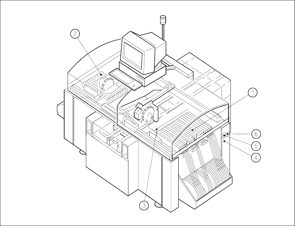
Fig. 7.1.1 Overview: location of the components changeover tables in the SIPLACE 80 S-20
Key to Fig. 7.1.1
1 Components changeover table with feeder modules, table 1, location 1 (tracks 1 to 120)
2 Components changeover table with feeder modules, table 2, location 3 (tracks 1 to 120)
3 Empty tape cutter unit (table 1)
4 Compressed air connection, components table pneumatic system, location 1
5 Interface connector for components supply location, connection of communications unit
6 Main power plug for connection of power supply (transformer) components table, location 1