F5 SERVICE MAUNAL.pdf - 第288页
8 IC Head S IPLACE 80S-20/F4 Service Manual 8.5 Servicing W ork on the Pneum atic System Edition 01/97 8 - 26
SIPLACE 80S-20/F4 Service Manual 8 IC Head
Edition 01/97 8.5 Servicing Work on the Pneumatic System
8 - 25
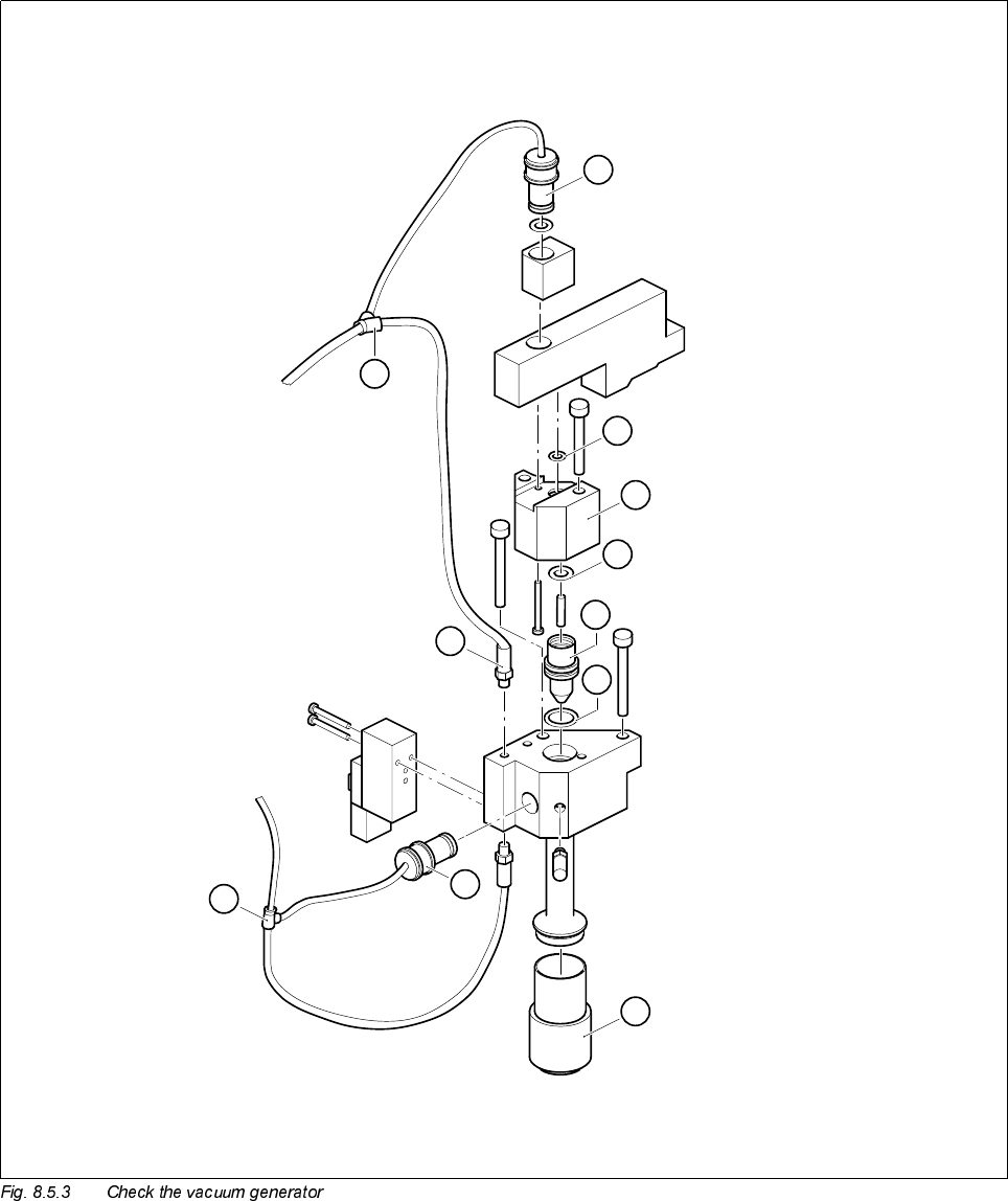
Key to Fig. 8.5.3
1 Collet bush PK-3 2 O-ring 3 x 1
3 O-ring 5 x 1.5 4 Vacuum nozzle for IC head
5 O-ring 8 x 1 6 Silencer
7 Collet bush PK-3 8 Hose coupling T-PK-3
9 Nipple with male threaded end 10 Hose coupling T-PK-3
A Remove spacer
8
6
1
7
5
9
10
4
3
2
A
8 IC Head SIPLACE 80S-20/F4 Service Manual
8.5 Servicing Work on the Pneumatic System Edition 01/97
8 - 26

SIPLACE 80S-20/F4 Service Manual 8 IC Head
Edition 01/97 8.6 Measure Nozzle Changer
8 - 27
0HDVXUH1R]]OH&KDQJHU
7RROV(TXLSPHQW
'HWHUPLQH;<&RRUGLQDWHVRIWKH1R]]OH*DUDJHV
● Select the following menu sequence from the SITEST program:
Functions ↵ Nozzle changer ↵ Nozzle changer IC head ↵ Calibrate nozzle changer complete
'HWHUPLQH1R]]OH3LFN8S$QJOH
The nozzle pick-up angle is the angle at which the nozzle is removed from the garage.
● Connect the test box as described in the Adjusting Instructions.
● Place a nozzle on the nozzle support (spring steel sheet).
● Deactivate the dr axis.
● Manually turn the sleeve until the nozzle can be moved into the garage.
● Read the corresponding dr axis value on the test box.
● Use a DOS editor to enter this value.
PLEASE NOTE
It is generally sufficient to determine the value for one nozzle and then to use this value for the other noz-
zles.
The values in the test program for ’pick-up at d pos. or ’lock in place at d pos.‘ are used only to pick-up or
set down the nozzles correctly. They are not saved.
'HWHUPLQH3LFN8S+HLJKW
● Select the following menu sequence from the SITEST program:
Functions ↵ Nozzle changer ↵ Nozzle changer IC head ↵ Pick-up or return nozzle. The correct pick-up
height is determined by picking up and returning the nozzle.
)URPLWHPQXPEHU
SITEST program V ≥ 203.000
Nozzle removal tool 00311448-01
Test box
Adjusting Instructions