F5 SERVICE MAUNAL.pdf - 第129页
SIPLACE 80S -20/F4/F4-6/F5 Service Manual 5 Gantries Edition 09/99 5.6 Replacing the Tension Roller for the Y-axis Toothed Belt 5 - 21 5.6 Replacing the T ension Roller for the Y -axis T oothed Belt 5.6.1 Spare Parts, Au…
5 Gantries SIPLACE 80S-20/F4/F4-6/F5 Service Manual
5.5 Replacing the Drive Motor of the Y Axis Edition 09/99
5 - 20
5.5.3 Installation
● Fit the new motor using the mounting screws.
● Restore the motor’s electrical connections (depending on the gantry)
NOTE
Route your cables with care.
● Tension the cut toothed belt as described in Table 5.5 - 1.
● Fit the components table support and the sliding plate holder.
● Replace the empty tape cutter and restore all electrical and pneumatic connections.
● Carry out a complete adjustment of the y axis (see adjustment instructions).
Key to Fig. 5.5.1
.
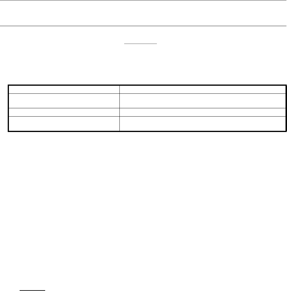
Length of the toothed belt 2540 mm
Measurement position on the toothed belt
600 mm from the center of the motor pinion to the center of the ten-
sioning roller on the motor side (see item A in Fig. 5.5.1)
Frequency of the new toothed belt 46 Hz ± 1 Hz
Frequency of the toothed belt once run in
(t
≥
5 hours
)
46 Hz ± 1 Hz
Table 5.5 - 1 Required adjustment of the cut toothed belt for the y axis
1 Stop (remove only in F
4
, F
4
-6 or
F
5
machines
2 Sliding plate and sliding plate holder
3 Y motor 4 Y-axis toothed belt
5 Tension rollers 6 X gantry
7 Y-axis deflection roller A Adjustment for the toothed belt tension: 600 mm distance

SIPLACE 80S-20/F4/F4-6/F5 Service Manual 5 Gantries
Edition 09/99 5.6 Replacing the Tension Roller for the Y-axis Toothed Belt
5 - 21
5.6 Replacing the Tension Roller for the Y-axis
Toothed Belt
5.6.1 Spare Parts, Auxiliary Materials and Equipment
– 1 tension roller, Y axis, from item no. 00321607-02
– Belt tension measuring device, from item no. 00326015-01
5.6.2 Removal
NOTE
You should comply with the safety instructions in Section 1.
● Loosen the Y-axis toothed belt on the tension rollers using a hexagon socket screw key, size 8
(see Fig. 5.5.1
).
● Loosen the three M6 hexagon socket screws which fit the tenion roller (see Fig. 5.5.1).
5.6.3 Installation
● Fit the new tension roller using the fastening screws.
● Tension the cut toothed belt in accordance with Table 5.5 - 1 on page 5 - 20.
● Carry out adjustment for the Y axis (see adjustment instructions).

5 Gantries SIPLACE 80S-20/F4/F4-6/F5 Service Manual
5.7 Exchanging the X-/Y-Trailing Cable Edition 09/99
5 - 22
5.7 Exchanging the X-/Y-Trailing Cable
5.7.1 Safety Instructions
DANGER O O O
Machines of the SIPLACE family are powered by 3 x 400 V +/- 10 %, 50/60 Hz line voltage.
As a consequence, parts of the system conduct dangerous levels of electricity. Inside the machine base these
levels are present even when the main switch is OFF!
During all work with the machine, you must comply with the higher level safety instructions in Section 1 of
this service manual. During all work inside the machine base in particular, observe the more stringent safety
regulations DIN EN 60204 (formerly VDE 0113).
For all following jobs the machine must be switched OFF and isolated from the mains. In addition, the
compressed air intake must be switched OFF at the main valve of the compressed air unit in the machine
base. The compressed air lines must be vent by opening the air relief valve.
Secure the machine carefully to prevent unauthorized restarting.
Follow the instructions regarding residual voltages in Section 1 when the machine base doors are removed
(terminal panel/servo cabinet).
Comply with regulations on ESDs during all work on the circuit boards (see Section 1).
To perform the work it is best if the relevant component table is dismantled.
2 people are required to dismantle the exchangeable component table !
During all of the work, secure the machine against other people and against unauthorized starting as
described in Section 1.
Proceed in the following order.