F5 SERVICE MAUNAL.pdf - 第25页
SIPLACE 80S-20/F4/F4-6/F5 Serv ice Manual 1 Operational Safety Edition 04/98 1.2 Safety equipment 1 - 15 1.2.2 Guard on the input / outpu t conveyor DANGER The guar d must always be s et to th e heigh t of the PCB to be …
1 Operational Safety SIPLACE 80S-20/F4/F4-6/F5 Service Manual
1.2 Safety equipment Edition 04/98
1 - 14
1.2.1.1 General
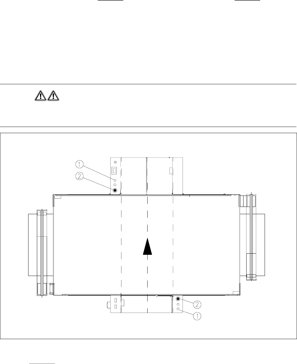
The gantry positioning range is covered by two protective covers. If you want to open the protective covers,
first press the Stop button (item 1 in Fig. 1.2.2
) or the emergency stop button (item 2 in Fig. 1.2.2). The power
to the gantry axes will be switched off and the gantries will stop immediately.
If you open one of the protective covers or a guard on the incoming or outgoing conveyor, the power to the
gantry axes will be switched off and they will stop immediately.
If the key switch is closed (position
I
), you can continue to pace the star at reduced speed while the protective
covers are open.
Placement will stop if you press the emergency stop button. You can then either cancel or continue placement
of the PCB. The protective covers at the sides can be opened in order to refill with components when the
machine has stopped.
WARNING
The protective covers must only be opened, with the key switch closed (position
I
), by appropriately qualified
and trained personnel.
Fig. 1.2.2 Stop and emergency stop buttons
.H\WR Fig. 1.2.2
1 Stop button 2 Emergency stop button
SIPLACE 80S-20/F4/F4-6/F5 Service Manual 1 Operational Safety
Edition 04/98 1.2 Safety equipment
1 - 15
1.2.2 Guard on the input / output conveyor
DANGER
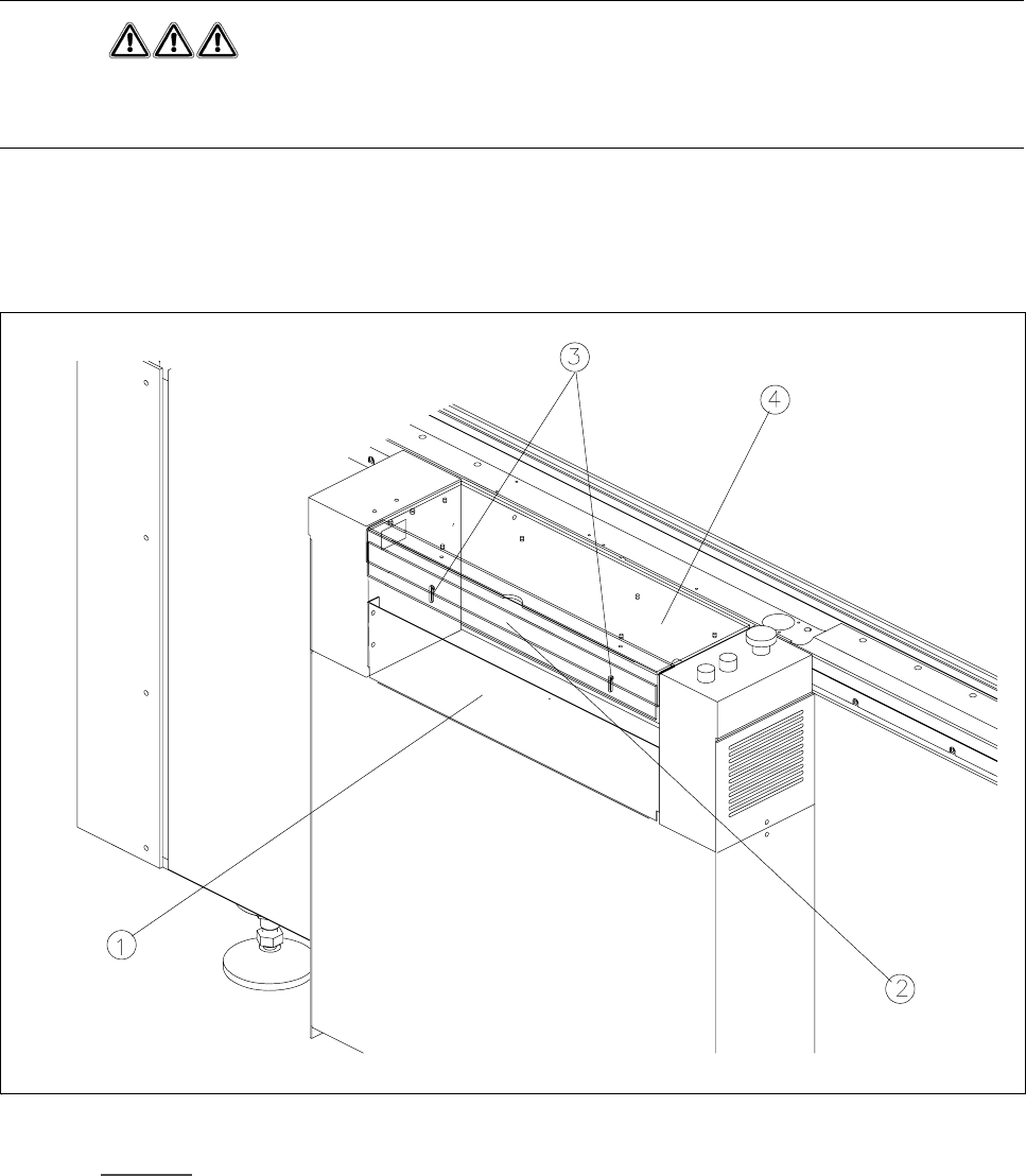
The guard must always be set to the height of the PCB to be processed. Ensure that the gap between the
guard and the safety bar is as small as possible.
Guards are fitted on the input and output belts of the PCB conveyor.
The height of the guard must be set using the slots so that the processed PCB can travel through.
Fig. 1.2.3 Guard on SIPLACE 80S20/F
4
/F
4
-6/F
5
- Key to Fig. 1.2.3
1 Safety bar (fixed) 2 Guard (adjustable)
3 Slots for adjusting the height 4 Cover
1 Operational Safety SIPLACE 80S-20/F4/F4-6/F5 Service Manual
1.2 Safety equipment Edition 04/98
1 - 16
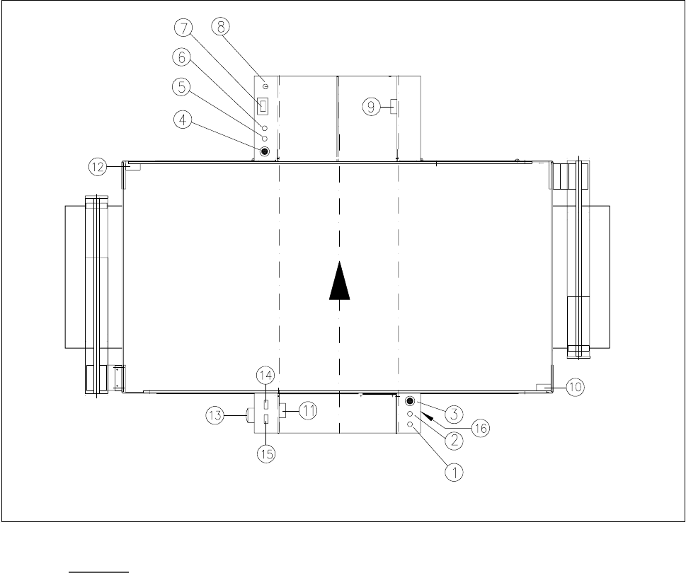
1.2.3 Emergency stop button, protective cover switch and key switch
Fig. 1.2.4 Location of the buttons and protective contactor combination K1, K2
.H\WR )LJ
1 Stop button
2 Start button
3 Emergency stop button
4 Emergency stop button
5 Start button
6 Stop button
7 Component counter
8 Key switch open: position 0 for normal mode
closed: position I for service purposes
9 Protective cover switch (output conveyor, 00303617-xx)
10 Protective cover switch (right, 00321417-xx)
11 Protective cover switch (input conveyor, 00303614-xx)
12 Protective cover switch (left, 00321416-xx)
13 Main switch
14 Protective contactor combination K1
15 Protective contactor combination K2
16 Compressed air unit