F5 SERVICE MAUNAL.pdf - 第290页
8 IC Head S IPLACE 80S-20/F4 Service Manual 8.6 Measure Nozz le Changer Edition 01/97 8 - 28 ,QVHUW1R ]]OHLQWR1R]]OH&KDQJ HU ● Manuall y inser t the n ew or serv iced noz zles in th e correct order i nto th…

SIPLACE 80S-20/F4 Service Manual 8 IC Head
Edition 01/97 8.6 Measure Nozzle Changer
8 - 27
0HDVXUH1R]]OH&KDQJHU
7RROV(TXLSPHQW
'HWHUPLQH;<&RRUGLQDWHVRIWKH1R]]OH*DUDJHV
● Select the following menu sequence from the SITEST program:
Functions ↵ Nozzle changer ↵ Nozzle changer IC head ↵ Calibrate nozzle changer complete
'HWHUPLQH1R]]OH3LFN8S$QJOH
The nozzle pick-up angle is the angle at which the nozzle is removed from the garage.
● Connect the test box as described in the Adjusting Instructions.
● Place a nozzle on the nozzle support (spring steel sheet).
● Deactivate the dr axis.
● Manually turn the sleeve until the nozzle can be moved into the garage.
● Read the corresponding dr axis value on the test box.
● Use a DOS editor to enter this value.
PLEASE NOTE
It is generally sufficient to determine the value for one nozzle and then to use this value for the other noz-
zles.
The values in the test program for ’pick-up at d pos. or ’lock in place at d pos.‘ are used only to pick-up or
set down the nozzles correctly. They are not saved.
'HWHUPLQH3LFN8S+HLJKW
● Select the following menu sequence from the SITEST program:
Functions ↵ Nozzle changer ↵ Nozzle changer IC head ↵ Pick-up or return nozzle. The correct pick-up
height is determined by picking up and returning the nozzle.
)URPLWHPQXPEHU
SITEST program V ≥ 203.000
Nozzle removal tool 00311448-01
Test box
Adjusting Instructions
8 IC Head SIPLACE 80S-20/F4 Service Manual
8.6 Measure Nozzle Changer Edition 01/97
8 - 28
,QVHUW1R]]OHLQWR1R]]OH&KDQJHU
● Manually insert the new or serviced nozzles in the correct order into the nozzle changer.
● Using the nozzle removal tool, turn each nozzle to the left in order to lock it in place in the nozzle changer.
● Select the station menu functions Gantry 1 ↵ Nozzle changer configuration to display the assignment and
check the desired and actual values of the assignment for consistency.
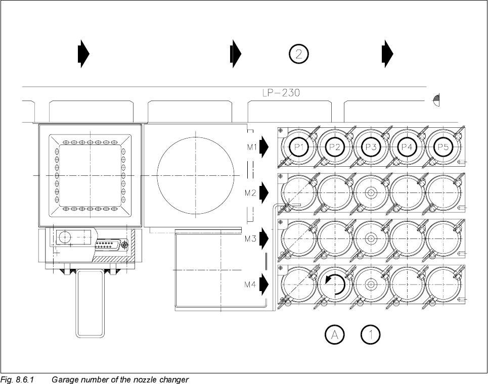
The general assignments are shown in the following diagram.
Key to Fig. 8.6.1
1 Nozzles 2 PCB transport direction
A Lock nozzle in place by turning to the left

SIPLACE 80S-20/F4 Service Manual 8 IC Head
Edition 01/97 8.7 Disassemble and Reassemble IC Head
8 - 29
'LVDVVHPEOHDQG5HDVVHPEOH,&+HDG
7RROV(TXLSPHQW
6SDUH3DUWV
'LVDVVHPEOHWKH,&+HDG
● Detach all power cables and air hoses.
● Loosen the four fixing screws for the IC head as shown in Fig. 8.7.1.
● Remove the IC head and fix it to the mounting rack for the IC head.
)LWWKH,&+HDG
● Fix the IC head in place using the 4 fixing screws. Please note that the screws are of different lengths! (see
Fig. 8.7.1 page 8 - 30)
● Attach the power cables to the IC head board (see Fig. 8.2.2 page 8 - 8).
● Reconnect the air hoses.
● Edit the zero point correction values for the z and dr axes in the MA data.
● Check the dynamic performance of the servo axes with reference to the Adjusting Instructions and adjust
the axes.
● Measure the automatic placement machines with reference to the IC head.
)URPLWHPQXPEHU
Slotted head screw driver, set
Mounting rack for the IC head 00318295-01
SITEST program V ≥ 203.000
Test box
Adjusting Instructions
)URPLWHPQXPEHU
IC head for CAN bus 00322583S01