F5 SERVICE MAUNAL.pdf - 第469页
14 Pneumatic Cutter Service Manual SIPLACE 80S- 20/F4/F5 14.1 Pneumatic Cutter and Empty-Tape Duct Edition 04/98 14 - 11 ● Push t he PRY DEOH blade ( includ ing the rail) in paral lel u ntil it is in th e mount ing posi…
Service Manual SIPLACE 80S-20/F4/F5 14 Pneumatic Cutter
Edition 04/98 14.1 Pneumatic Cutter and Empty-Tape Duct
14 - 10
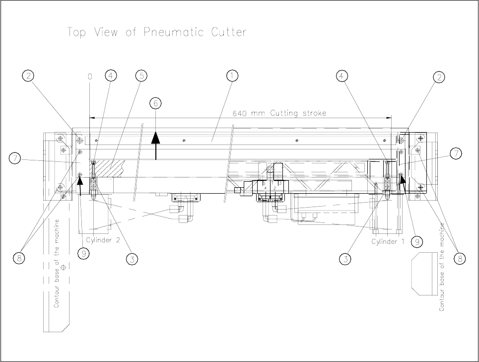
Fig. 14.1.5 Removing/Installing Stationary and Movable Blades (including rail)
Key:
1) Stationary blade including rail 2) Fastening of the stationary blade (including rail):
(rail is not removed when blade rotated 180°) 2 Socket hex bolts, M6 x 30
3) Gelenk 4) Fastening: articulated joint in the movable blade:
Socket hex bolt, M4 x 25
5) Movable blade including rail 6) Direction for removing the movable blade
(rail is not removed when blade rotated 180°)
7) Holddown with spacer under it 8) Fastening of the holddown:
2 Socket hex bolts, M4 x 25
9) Loosen these bolts to remove the cover plate
● Loosen the bolts fastening the VWDWLRQDU\blade at left and right: see Fig. 14.1.5 -> 2).
● Take hold of the stationary blade by its ends and lift it (and the rail) out of the machine.
● First of all, place it in exactly the position LQZKLFKLWZDVLQVWDOOHG(right end UHPDLQVon the right) RU
PDUNWKHSUHYLRXVmounting position with a water-insoluble marker
● Holding the articulated joint with a size 10 open-end wrench (see Fig. 14.1.5 -> 3) oosen the Fastening the
articulated joint in the movable blade (1 bolt each at right and left: see Fig. 14.1.5 -> 4).

14 Pneumatic Cutter Service Manual SIPLACE 80S-20/F4/F5
14.1 Pneumatic Cutter and Empty-Tape Duct Edition 04/98
14 - 11
● Push the
PRYDEOH
blade (including the rail) in parallel until it is in the mounting position of the stationary
blade (direction of movement: see Fig. 14.1.5 -> 6). When it is in this position, lift the movable blade
(including the rail) out of the cutter.
● )LUVWPDUNWKHPRXQWLQJSRVLWLRQRIWKHPRYDEOHEODGH
with a water-insoluble marker
OHIWHQG OHIW
VLGH
● Remove the deflector plate from the rail by the movable blade (4 M3 bolts: see Fig. 14.1.4 -> 6, 7) and
mount on the
RSSRVLWH
long side of the rail.
14.1.7.2 Installation of the Blades
● Turn the movable blade 180 ° to the previous marked mounting position.
-> The left-hand end of the blade must now be
on the right.
● Insert the movable blade (including rail) into the cutter in this angle of rotation and push it in parallel
back into the original mounting position.
● Screw the bolt to fasten the articulated joint (Fig. 14.1.5 -> 4) back on the left and right of the movable
blade.
NOTE:
Make certain that the midline / open-end wrench surface of the articulated joint is at right angles to the fric-
tion surface of the movable blade (see Fig. 14.1.8 -> 5 and 6).
● Using the size 10 open-end wrench to hold the appropriate articulated joint, tighten both bolts.
● Afterwards, rotate the stationary blade 180 ° to the original mounting position. Insert it into the cutter in
this position and tighten the bolts.
-> The right-hand end of the blade must now be on the
left.
● $VVHPEOH
the cutter in reverse order to disassembly, as described in Section 14.1.7.1.
● Carry out the “Final Steps” (see Section 14.1.17).
14.1.8 Exchanging the Stationary Blade and Movable Blade including
the Spacers
NOTE
The stationary blade and the movable blade, including the spacers, must always be exchanged as a set if
both cutting edges have been used, i.e., are dull.
The blades which are removed can be reground at the Siemens facility.
The cutter remains installed in the machine.
● To remove the two blades, proceed as described in Section 14.1.7.
Service Manual SIPLACE 80S-20/F4/F5 14 Pneumatic Cutter
Edition 04/98 14.1 Pneumatic Cutter and Empty-Tape Duct
14 - 12
● In addition, undo the fastening the holddowns (at right and left of the cutter: see Fig. 14.1.5 -> 7, 8).
Remove both holddowns
DQG
the
VSDFHUV
underneath them.
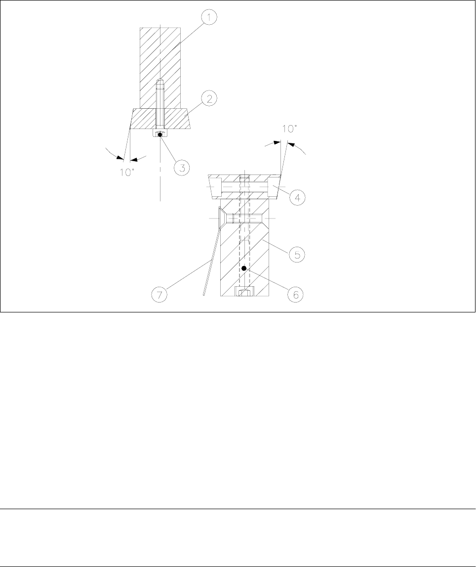
Fig. 14.1.6 Mounting New and Movable Blades; Checking the Mounting position of the Blades
Key:
1) Rail for stationary blade 2) Stationary blade
3) 5 Socket hex bolts, M4 x 20 *) 4) Movable blade
5) Rail for movable blade 6) 5 Socket hex bolts, M4 x 45 *)
7) Deflector plate
*) Loctite no. 243 used on bolts screwed in.
● Dismantle the stationary blade and the movable blade from the rail (see Fig. 14.1.6).
-> The bolts are secured with Loctite no. 243, so considerable strength may be necessary.
● Place a little Loctite no. 243 (item no.: see Section 14.1.3) on the 5 bolts securing each.
WARNING O O
The rotational position of the blades - which can be recognized from the 10° bevel - must be correct (Fig.
14.1.6 and Fig. 14.1.4).
● Bolt the previously removed, FRUUHFWrail onto the QHZPRYDEOHDQGQHZVWDWLRQDU\blade (item nos. of
spare parts: see Section 14.1.2).
● Insert the WZRQHZVSDFHUV (item no.: see Section 14.1.2) into the cutter (see Fig. 14.1.5).