F5 SERVICE MAUNAL.pdf - 第274页
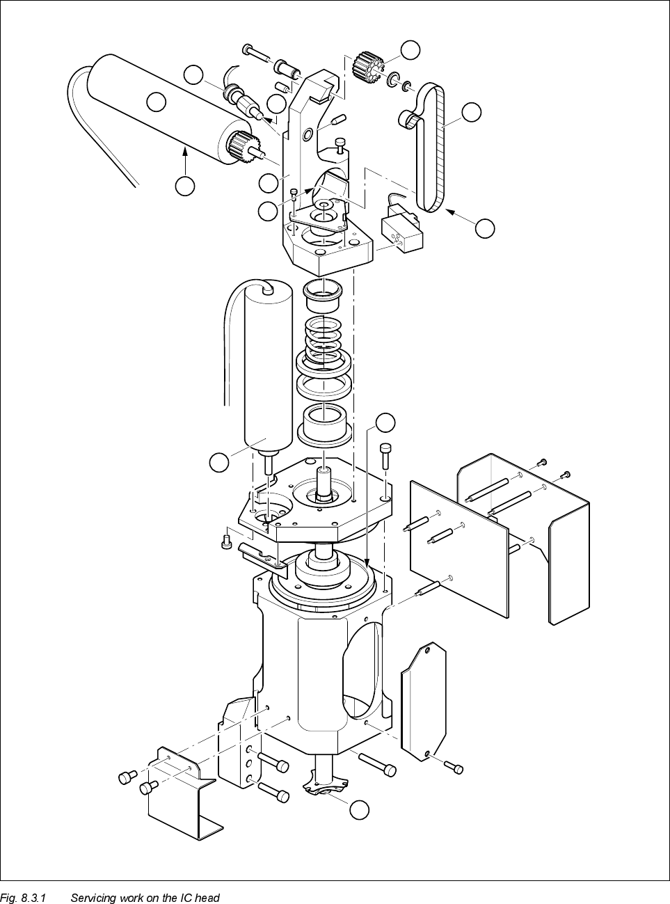
8 IC Head S IPLACE 80S-20/F4 Service Manual 8.3 Servicing W ork on the Z Axis Edition 01/97 8 - 12 2 4 3 A B C 5 1 6 D 8 7

SIPLACE 80S-20/F4 Service Manual 8 IC Head
Edition 01/97 8.3 Servicing Work on the Z Axis
8 - 11
5HSODFHWKH(QG3RVLWLRQ%(52
See item 6 in Fig. 8.3.1 page 8 - 12
● Loosen the clamping screw for fixing the BERO.
● Replace the BERO.
● Position the BERO so that its end face is flush with the housing.
● Fix the BERO in place.
● Check that the BERO switches correctly.
$GMXVW$QWL5RWDWLRQ/RFNRQ%HDULQJ+RXVLQJ
See item 10 in Fig. 8.3.2 page 8 - 15
Two horizontal slots have been milled into the anti-rotation lock for adjustment purposes.
$GMXVWWKHDQWLURWDWLRQORFN
● Deactivate the z axis clamping device and push the sleeve up so that the bearing housing covers the end
face of the end position BERO (item 6, Fig. 8.3.1 page 8 - 12).
● Turn the bearing housing (item 11, Fig. 8.3.2 page 8 - 15) counterclockwise - viewed from above - towards
the mount (item 8, Fig. 8.3.1 page 8 - 12). This will activate the BERO.
● Now turn the bearing housing and the anti-rotation lock (items 10 and 11, Fig. 8.3.2 page 8 - 15) clockwise
towards the mount. The BERO should not be deactivated.
● If this is not the case, loosen the two M2 screws on the anti-rotation lock and push the lock towards the
mount. Tighten the two screws.
PLEASE NOTE
The gap between the anti-rotation lock and the mount should be between 0.5 mm and 1 mm.
● Check that the BERO switches correctly by moving the sleeve up and down several times. To do this,
loosen the z axis clamping device.
● Deactivate the clamping device and move the sleeve up and down. The end position BERO (item 6, Fig.
8.3.1 page 8 - 12) must switch.
8 IC Head SIPLACE 80S-20/F4 Service Manual
8.3 Servicing Work on the Z Axis Edition 01/97
8 - 12
2
4
3
A
B
C
5
1
6
D
8
7

SIPLACE 80S-20/F4 Service Manual 8 IC Head
Edition 01/97 8.3 Servicing Work on the Z Axis
8 - 13
Key to Fig. 8.3.1
5HSODFHWKH6OHHYH
See item 12 in Fig. 8.3.2 page 8 - 15
If the sleeve has been broken the head has to be repaired by Siemens because the ball bearings of the z-axis
may have been damaged, too. If the shaft seizes due to the ball bearings of the z-axis or the z-clamping the
head must always be repaired by a Siemens.
WARNING ∆
!
This servicing work may only be carried out by authorized and trained personnel.
● Remove the clip (item 7, Fig. 8.3.2 page 8 - 15) from the vacuum connector at the top of the sleeve.
● Pull the vacuum hose off the vacuum connector (item 8).
● Fix the sleeve removal mount to the lower end of the sleeve.
● Firmly hold the sleeve and the sleeve removal mount and then loosen the hexagonal nut (item 9) at the top
of the sleeve using the size 13 open-ended spanner.
● Using a 2 mm hexagon socket head spanner, loosen the fixing screw (item 5) on the clamping part
(item 6).
WARNING ∆
!
Before you remove the sleeve, loosen the z axis clamping device by pressing the red push-button on the
solenoid valve for the z axis clamping device (see items 4 and A, Fig. 8.2.1 page 8 - 4).
● Pull the sleeve down and out.
To reassemble the sleeve
● Insert the new sleeve from the bottom.
1 Synchronizing disc Al 10 T2/26-0 2 Star with spring steel sheet
3 Friction wheel 4 Motor/tacho for dr axis
5 Motor/tacho for z axis 6 End position BERO
7 Synchroflex 6 T2/220 toothed belt 8 Mount
Mounting instructions
A Toothed belt tension: 190 Hz ± 5 Hz B The end face of the z motor must be flush with the mount
C Zero point correction value:
0.4 mm = 10 digits
D The end face of the BERO must be flush with the mount