F5 SERVICE MAUNAL.pdf - 第95页
SIPLACE 80S-20/F4 Service Manual 4 Power Supply Edition 01/96 4.2 Power Supply Unit 4 - 9 4.2 Po wer Supply Unit 4.2.1 Genera l The power supply unit and th e main switch a re acc ommoda ted in the m achine b ase (se e F…
4 Power Supply SIPLACE 80S-20/F4 Service Manual
4.1 Introduction Edition 01/96
4 - 8

SIPLACE 80S-20/F4 Service Manual 4 Power Supply
Edition 01/96 4.2 Power Supply Unit
4 - 9
4.2 Power Supply Unit
4.2.1 General
The power supply unit and the main switch are accommodated in the machine base (see Fig. 4.1.1). In front
of the power supply unit there is a metal panel which is held in place by means of two hexagon socket screws.
The unit itself is fastened to the machine base with one hexagon socket screw.
To take measurements at the power supply unit proceed as follows:
● Switch onthe placement machine and disconnect it from the power supply.
● Undo the power supply unit mounting screws and pull the unit out.
● Support the unit if necessary.
CAUTION
QQQ
Make sure you do not damage the cable or put tensile stress on the snap-in connections.
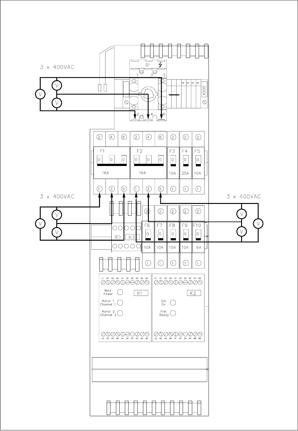
4.2.2 Supply Voltages at the Front of the Unit
At the front of the power supply unit you will find automatic circuit-breakers F1-F10, power circuit-breaker Q1
and contactors K1-K3 (see Fig. 4.2.1).
● Reconnect the placement machine to the power supply.
● Switch on the main switch and carry out your measurements. Make sure you comply with the safety
instructions in Section 1.
● At automatic circuit-breaker F1 you should measure 3 x 400 VAC (see Fig. 4.2.1).
● Switch on automatic circuit-breaker F1. At automatic circuit-breaker F2 you should measure 3 x 400 VAC
(see Fig. 4.2.1).
● Switch on automatic circuit-breaker F2. Check to see whether the software relay (LED) has energized.
Press the Control on button. At inrush current limiter A1 and at transformer T2 you should measure 3 x
400 VAC (see
Fig. 4.2.3)
.
● At automatic circuit-breaker F3 you should measure 230 VAC against ground (see Fig. 4.2.2).
● Switch on automatic circuit-breaker F3. At transformer T1 you should measure 230 VAC against N (see
Fig. 4.2.3).
● At automatic circuit-breaker F4 you should measure 85 V direct voltage against ground (see Fig. 4.2.2).
● At automatic circuit-breaker F5 you should measure 60 V direct voltage against ground (see Fig. 4.2.2).
● At automatic circuit-breaker F6 you should measure 30 V direct voltage against ground (see Fig. 4.2.2).
● At automatic circuit-breaker F7 you should measure 24 V alternating voltage against ground (see Fig.
4.2.2).
● At automatic circuit-breaker F8 you should measure 8 V direct voltage against ground (see Fig. 4.2.2).
● At automatic circuit-breaker F9 you should measure 30 V direct voltage against ground (see Fig. 4.2.2).
● At automatic circuit-breaker F10 you should measure 24 V alternating voltage against ground (see Fig.
4.2.2).
4 Power Supply SIPLACE 80S-20/F4 Service Manual
4.2 Power Supply Unit Edition 01/96
4 - 10
Fig. 4.2.1 Front of power supply unit C0952 - measuring voltages