F5 SERVICE MAUNAL.pdf - 第177页
SIPLACE 80S-20/F4 Service Manual 6 PCB Handling Edition 01/96 6.4 Conveyor Toothed B elts 6 - 21 6.4.1.2 Function T est ● Carry ou t a func tion tes t as spec ified in the adj ustment i nstruct ions. NOTE OOO With the fu…
6 PCB Handling SIPLACE 80S-20/F4 Service Manual
6.4 Conveyor Toothed Belts Edition 01/96
6 - 20
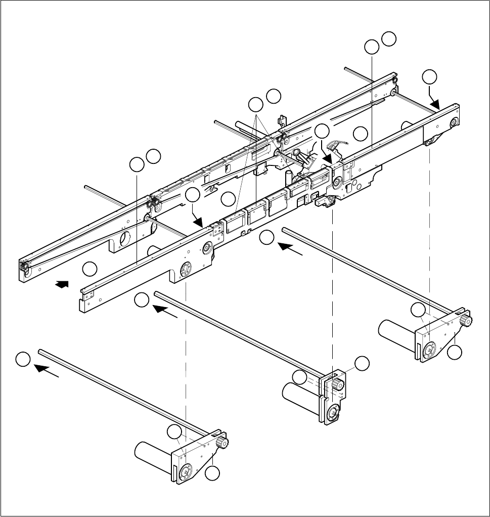
Fig. 6.4.1 Removing the conveyor toothed belt on the fixed side of the conveyor
Key to Fig. 6.4.1
1 Input conveyor 2 Center conveyor
3 Output conveyor 4 Guide rails
5 Drive unit of input or output conveyors 6 Center conveyor drive unit
D
3
1
2
5
6
B
B
C
B
C
5
C
4
A
4
A
4
A
D
D

SIPLACE 80S-20/F4 Service Manual 6 PCB Handling
Edition 01/96 6.4 Conveyor Toothed Belts
6 - 21
6.4.1.2 Function Test
● Carry out a function test as specified in the adjustment instructions.
NOTE OOO
With the function test do not fail to comply with the safety instructions in Chapter 1.
● Unlock the key-operated switch before performing function testing and making adjustments. This will allow
you to take measurements at the motors with the protective cover open. However the gantry axis systems
will be in a de-energized state.
NOTE O
When you have finished the function test do not forget to lock the key-operated switch again, stowing the
key in a place where unauthorized persons have no access to it.
6.4.2 Replacing the conveyor toothed belt on the movable side of the
board conveyor
These instructions apply to all three board conveyors.
Spare parts, auxiliary materials and equipment
Synchroflex toothed belt, Item No. 00200196-01
SITEST program
6.4.2.1 Changing the conveyor toothed belt on the movable side of the board con-
veyor
NOTE OOO
You should also comply with the safety instructions in Chapter 1.
● Select the maximum width setting for the board conveyor so that you can carry out servicing work unim-
peded.
● Move the gantry or gantries to outside the board transportation area.
● Switch off the machine at the main switch and disconnect it from the main power supply.
● Make sure that the machine cannot be switched on while you are carrying out servicing work.
● Slacken off the M3 hexagon socket screws which fasten the guide rails to the fixed side of the conveyor in
question (A).
● Undo the two M3 hexagon socket screws of the sonar BERO mount (B). (This step is not needed with the
center conveyor.)
● Carefully place the mount together with the sonar BERO on the machine base. Make sure that you do not
kink the connecting cable or bend it too tightly.
● Remove the cable shoes from the motor terminals.
6 PCB Handling SIPLACE 80S-20/F4 Service Manual
6.4 Conveyor Toothed Belts Edition 01/96
6 - 22
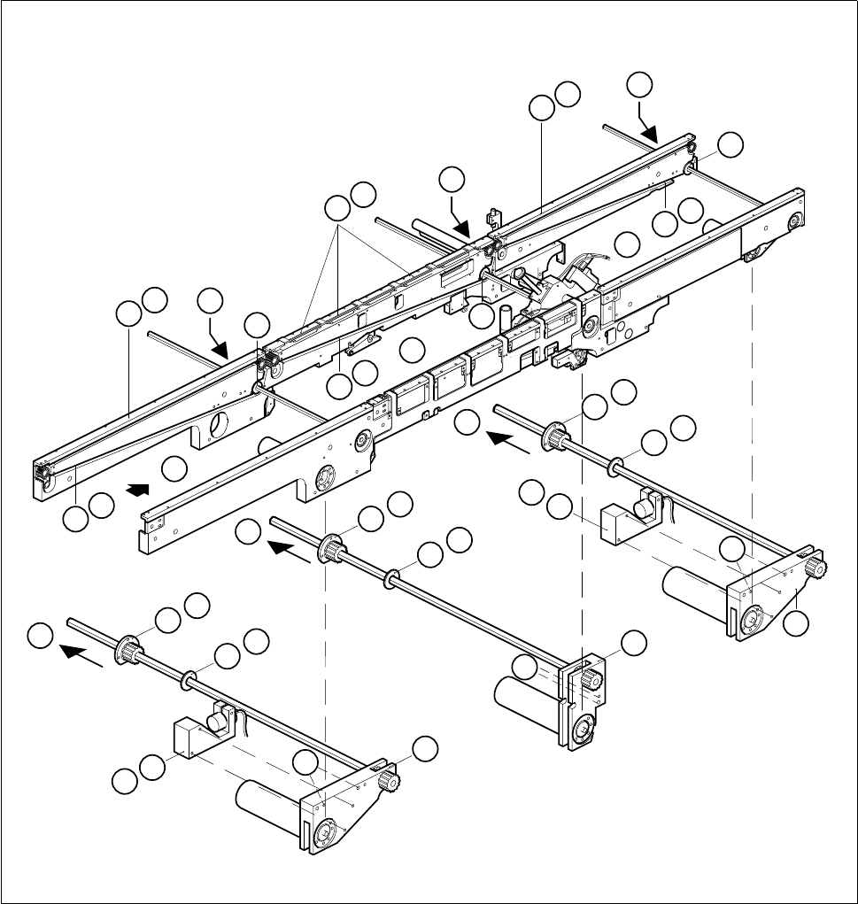
Fig. 6.4.2 Removing the conveyor toothed belt on the movable side of the board conveyor
Key to Fig. 6.4.2
● Remove the cable shoes from the motor terminals.
● Remove the heat-shrinkable sleeve rings which attach the cable to the geared motor.
1 Input conveyor 2 Center conveyor
3 Output conveyor 4 Guide rails
5 Sonar BERO mount 6 Drive unit of the input and output conveyors
7 Center conveyor drive unit 8 Conveyor toothed belt
9 Disk 10 Flange
C
10
9
D
C
10
9
D
C
10
9
D
3
1
2
6
5
B
5
B
6
7
E
E
F
E
F
F
4
A
4
A
4
A
8
G
8
G
8
G
9
9
9
10
10
10