F5 SERVICE MAUNAL.pdf - 第444页
13 6-Segment Revolver Head (8000) SIPLACE 80S-20/F4 Service Manual 13.6 Star Complete E dition 07/97 13 - 30
SIPLACE 80S-20/F4 Service Manual 13 6-Segment Revolver Head (8000)
Edition 07/97 13.6 Star Complete
13 - 29
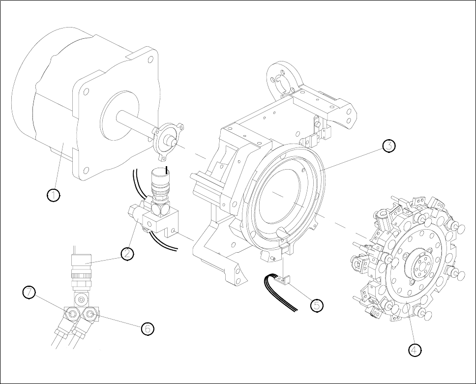
Fig. 13.6.1 Star complete with drive and forced air unit
1 Star motor
2 Forced air unit
3 Front part of the housing
4 Star complete
5 ’Z-axis at bottom’ sensor
6 Flow control for pick-up/placement circuit
7 Flow control for reject circuit
13 6-Segment Revolver Head (8000) SIPLACE 80S-20/F4 Service Manual
13.6 Star Complete Edition 07/97
13 - 30

SIPLACE 80S-20/F4 Service Manual 13 6-Segment Revolver Head (8000)
Edition 07/97 13.7 Replacing the Valve for Vacuum / Forced Air and Hose
13 - 31
13.7 Replacing the Valve for Vacuum / Forced Air and
Hose
PLEASE NOTE
This work may only be carried out by Siemens service technicians or by the customer’s appropriately trained
personnel.
Spare parts
Valve for SP6, from item no. 00324955S01
Plastic hose, silicone, 1.5 x 3.5, natural, from item no. 00323387S01
● Remove the front part of the placement head (see section 13.1.7).
● Remove the star complete (see section 13.6.1).
● Carefully remove the vacuum hose from the segment guide.
● Undo the two slotted head screws (M1.5 x 4) and remove the valve block (see Fig. 13.7.1).
● Watch out for the o-ring located in the base of the star.
● When re-installing the valve and vacuum hose proceed in the reverse sequence of operations.
● To fit the star complete, see section 13.6.2. To record the star axis zero point correction, see section
13.6.3.
ATTENTION ∆
!
∆
!
When fitting the valve block look out for the cutaway in the valve block and the o-ring in the star base. The cut-
away serves as a guide for the valve block.
NOTE
The vacuum hose must be cut precisely to length. Make sure it fits onto the segment guide without twisting.
ATTENTION ∆
!
∆
!
The vacuum hose must not rub against the adjacent vacuum hoses.