F5 SERVICE MAUNAL.pdf - 第366页
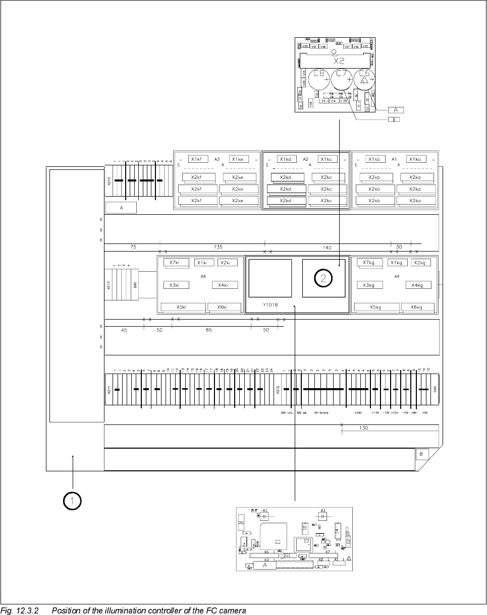
12 Vision s ystems SIPLA CE 80S-20/F4/F5 Service Manual 12.3 Replacing the flip-chip vision camera and illumination controller (SIPLACE 80F) Edition 09/99 12 - 14 Key to Fig. 1 2.3.2 1 Lef t-hand termi nal panel ( D0904)…

SIPLACE 80S-20/F4/F5 Service Manual 12 Vision systems
Edition 09/99 12.3 Replacing the flip-chip vision camera and illumination controller (SIPLACE 80F)
12 - 13
5HPRYLQJWKHIOLSFKLSLOOXPLQDWLRQFRQWUROERDUG<
NOTE
The illumination control board Y1019 is plugged into socket X7 of the ’Motherboard IC illumination Y1018’ in
the terminal panel ’left’ (D0904).
● Disconnect cable F0616-W2 from plug X2kk of the FC illumination control board
(see
➁
in Fig. 12.3.2 page 12 - 14).
● Remove the illumination control board Y1019 from the ’Motherboard IC illumination Y1018’.
)LWWLQJWKHIOLSFKLSYLVLRQFDPHUDDQGLOOXPLQDWLRQFRQWUROOHU
● When fitting, proceed in the reverse sequence of actions as described in Section 12.3.3, page 12 - 11 and
Section 12.3.4, page 12 - 13.
● Make sure that the board and plugs are seated properly.
● Be careful not to pinch or squash the cables during installation.
6HWWLQJZRUN
● Calibrate the flip-chip vision camera with the aid of the SITEST program.
● Once you have completed your setting work, fit the component changeover table back again.
SIPLACE 80S-20/F4/F5 Service Manual 12 Vision systems
Edition 09/99 12.4 Replacing the coplanarity laser module (SIPLACE 80F)
12 - 15
5HSODFLQJWKHFRSODQDULW\ODVHUPRGXOH6,3/$&(
)
6DIHW\LQVWUXFWLRQV
DANGER
You must not tamper with or make any modifications of any kind to the safety features or to the coplanarity
laser module ! The laser module must not be operated outside the placement machine and the protective cov-
ers on all sides must be closed.
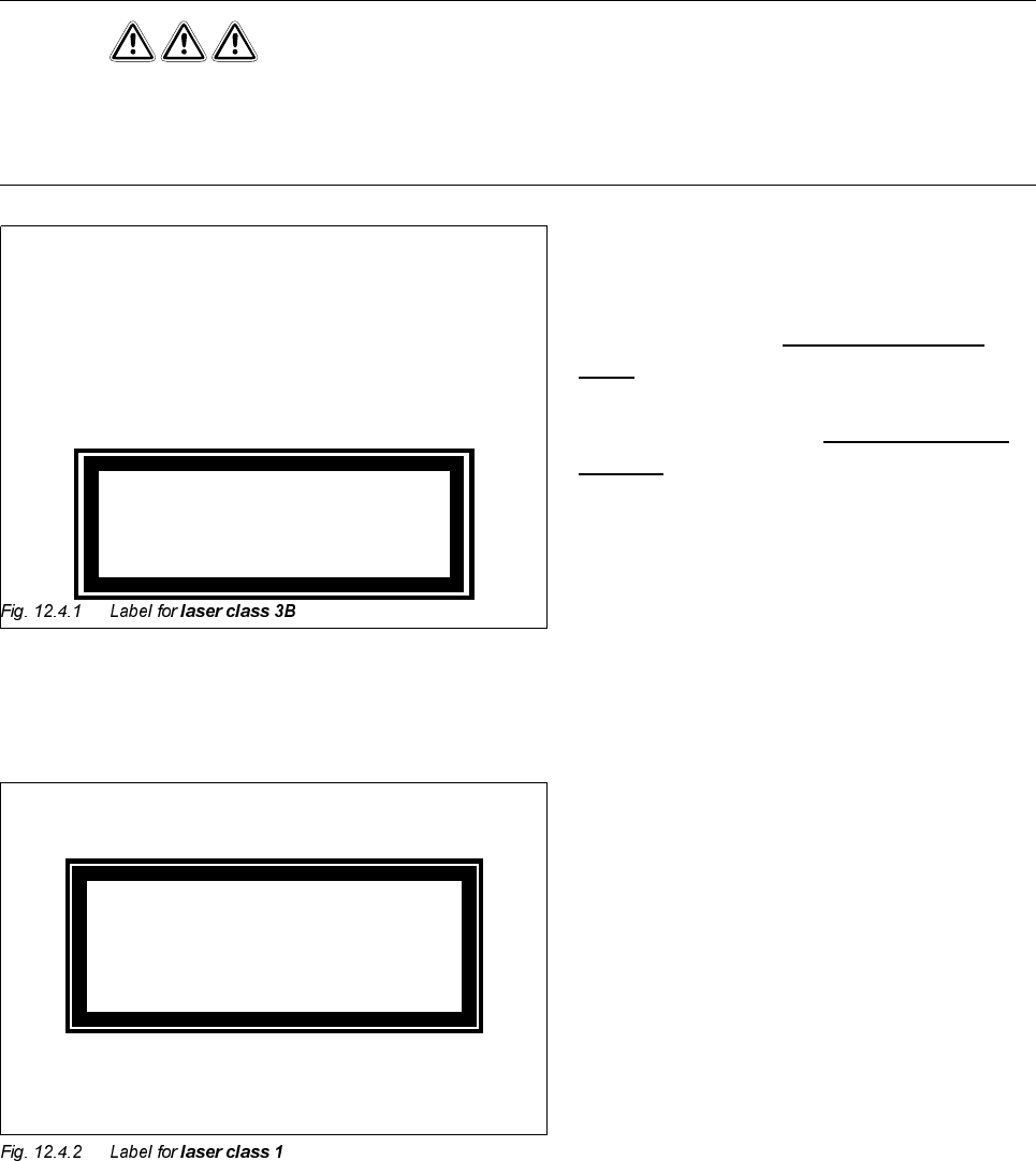
The coplanarity laser module - when no protec-
tive features are fitted - corresponds to
ODVHU
FODVV%
(Fig. 12.4.1)
This means potential
GDQJHUWRH\HVDQG
VNLQ
For this reason the safety features must not be
circumvented or disabled
XQGHUDQ\FLUFXP
VWDQFHV!
To enable the laser module to be operated in
ODVHUFODVV
with no danger to eyes or skin, the following safety
features have been installed in the machine:
The plug for the power supply (interlock line) is
permanently connected to the machine base.
This means that the laser module can be oper-
ated
RQO\ZKHQLWLVLQVLGHWKHPDFKLQH
The interlock line is connected in series with the
switches for the protective covers. This safety
feature cannot be disabled even by operating
the key-operated switch to bypass the safety
feature. This means that the laser module can
be operatedRQO\ZKHQWKHPDFKLQHLVFORVHG.
K
Invisible laser beam
Do not expose to beam
Laser class 3 B
2.4 mW max., 750 nm; as per IEC 825-1(1993)
Laser class 1