F5 SERVICE MAUNAL.pdf - 第152页
5 Gantries SIPLACE 80S-20/F4/F4-6/F5 Service Manual 5.7 Exchanging the X -/Y-Trailing Cable Edition 09/99 5 - 44 ● Mount th e Y-strai n relie f device exactly pa rallel to the Y-ga ntry rail (2 screws, si ze 3 Allen w re…

SIPLACE 80S-20/F4/F4-6/F5 Service Manual 5 Gantries
Edition 09/99 5.7 Exchanging the X-/Y-Trailing Cable
5 - 43
● Completely wrap the connect with Masking tape.
There are to be no remaining sharp edges which might damage the protective hose while the cable is
being inserted.
NOTE
When you re-install the old 7-tube hose, you have to wrap the individual ends of the tubes with Masking tape
as described in Section 5.7.7.1.
Always use a new protective hose (Item No.: see Section 5.7.2).
● Make certain that the protective hose is cut off at a smooth, right-angle at the top end. It is not to be
frayed. If an error is made, cut the protective hose properly with sharp scissors - outside of the machine.
-> During this process, cutt off as little as possible.
NOTE
No fabric fibers are to reach the machine.
● Carefully (!) push the cable/hose package, wrapped end first, into the new protective hose.
● Push the protective hose into the correct position relative to the Y-trailing cable hanger
(see Fig. 5.7.21).
5.7.7.5 Y-Gantry Area: Laying and Fastening the Y-Trailing Cable
CAUTION O
Make certain, that the cable supply chain ist mounted correct (= wide U-bracket must be at top, see Fig.
5.7.21 -> Check 1 !). Incorrect assembly causes demage during the placement sequence.
● If the cable supply chain was completely removed/exchanged, fasten the (new) cable supply chain in
the correct position with the top retaining bracket (wide) at the bottom of the Y-trailing cable hanger (two
M 4 screws, size 3 Allen wrench: see Fig. 5.7.1 and Fig. 5.7.21).
● Run the Y-trailing cable from the Y-trailing cable hanger to the Y-strain relief device:
● The cover band must be on the outside of the cable supply chain (see Fig. 5.7.21).
● Run the protective hose (with the cable/hose package) barely into the Y-trailing cable hanger. At the
top, the protective hose should only protrude about 0.5 cm past the first pin (next to the 90° bend in
the cable: see Fig. 5.7.20).
● In the area of the Y-trailing cable hangers place the single piece of ribbon cable previously dismantled
back on the protective hose and place the thin rubber sheet on it (see Fig. 5.7.11), such that these
parts project about 1 cm past the first pin. First fasten the trailing cable (y-axis) to its hanger with at
least one pin (see Fig. 5.7.11).
● Guide the protective hose in a loop along the cable supply chain and then on to the “Y-strain relief
device" next to the Y-gantry rail.
● Place the Y-trailing cable in the “Y-strain relief device" and insert the reversing pin.

5 Gantries SIPLACE 80S-20/F4/F4-6/F5 Service Manual
5.7 Exchanging the X-/Y-Trailing Cable Edition 09/99
5 - 44
● Mount the Y-strain relief device exactly parallel to the Y-gantry rail (2 screws, size 3 Allen wrench:
see Fig. 5.7.10).
CAUTION O
If the outer edges of the strain relief device are not exactly parallel to the Y-gantry rail, the protective hose
will move at an angle and will be damaged.
l Run the ribbon cables to the gantry board and make the plug-in connections:
● Lay the cables into the cable hanger from the side (see Fig. 5.7.8).
● Pull the cables down from the top enough so that they are lying completely flat next to the Y-gantry
rail.
● Remove the Masking tape from the connectors.
● Make the plug-in connections to the gantry board with the correct allocation (bottom cable -> connec-
tion to bottom plug-in connector).
● Put 3 ties back on the ribbon cable package (see Fig. 5.7.6).
l Connect the pneumatic hoses to the air distributor and fasten the hoses in place:
● Adjust the total length of the 7-tube hose at the bottom (right-angle cut).
● Run the 7-tube pneumatic hose to the air distributor next to the Y-gantry rail (see Fig. 5.7.9).
● Separate the hoses, starting at the point at which they emerge from the protective hose to the air dis-
tributor or remove any Masking tape on the ends of the hoses.
● Connect the hoses to the air distributor.
- Hoses No. 1 and 2 have to allocated correctly at the air distributor.
- To do so, refer to Fig. 5.7.18 and the diagram of the pneumatic system (S-20 or F4 / F5) from the
current folder of circuit diagrams.
● Fasten the Y-trailing cable in the correct position on the Y-trailing cable hanger:
● Bolt the bottom U-bracket of the cable supply chain to the “Y-strain relief device" (2 screws, size 3
Allen wrench: see Fig. 5.7.10).
● Check whether the cover band is on the outside of the cable supply chain and is undamaged. If not,
mount a new cover band (Item No.: see Section 5.7.2) on the entire length of the cable supply chain.
The cover band is placed under the top and bottom U-bracket.
● Insert the remaining 2 pins into the trailing cable hanger and push them to stop on the other side in
the slots (see Fig. 5.7.11). This fastens the Y-trailing cable in place.
● Run the Y-trailing cable along the cable supply chain such that it is just against it (see Fig. 5.7.21).
Pay attention to the following NOTE.
NOTE
The protective hose (with cable/hose package) is not to push against the cable supply chain.
There is not to be a visible space between chain and hose.
The protective hose (with cable/hose package) should be just touching the cable supply chain at both
gantry end positions.
SIPLACE 80S-20/F4/F4-6/F5 Service Manual 5 Gantries
Edition 09/99 5.7 Exchanging the X-/Y-Trailing Cable
5 - 45
● If the protective hose is too long, move the bottom end of the ribbon cable until the end of the hose
that is to be cut off is safely outside
the machine.
By doing so you ensure that no fabric fibers end up in the machine area during the subsequent
steps. Cut off the protective hose smooth and at right angles with sharp scissors. The end of the pro-
tective hose should not protrude over the Y-strain relief device.
● If the criteria in the above-mentioned NOTE are not observed, proceed as follows:
- If there is a space at the loop of the cable supply chain, loosen the fasteners on the Y-trailing
cable hanger again, pull the trailing cable on the protective hose up slightly and refasten it in that
position (see above).
- If the protective hose is pressing against the loop of the cable supply chain / touching too much,
try changing the position of the cable supply chain’s bottom U-bracket in the slots. If this does not
suffice, remove the Y-strain relief device again and move the trailing cable (protective hose with
contents)
an appropriate amount and put the reversing pin back in. Tighten the screws holding the Y-strain
relief device.
● Manually push the Y-gantry into the min. and max. travel position. In each case, make certain that the
above condition is fulfilled (see Fig. 5.7.21 -> Check 2 !).
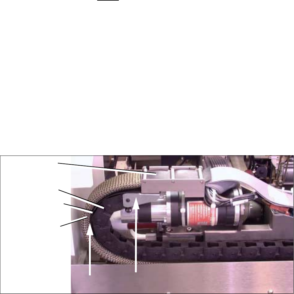
Fig. 5.7.21 Resetting and Checking the Correct Distance from “Protective Hose to Cable Supply Chain”,
Checking the correct assembly of U-bracket (Example for F4/F5)
● Attach the plug-in connector of the 2 ribbon cables on the top to the “Large Axis” conversion board. Check
to ensure that the plug-in connectors are securely seated.
● Install the cover over the “Large Axis” conversion board (3 screws, size 2 Allen wrench). Perform the
"Final Steps".
Y-trailing cable
completely
Cable supply chain
bolted in placet
Cover band
inserted
Protective hose
Check 2 !
assembled
Check 1 !