F5 SERVICE MAUNAL.pdf - 第476页
Service Manual SIPLACE 80S-2 0/F4/F5 14 Pneumatic Cut ter Edition 04/98 14.1 Pneumatic Cutter and Empty-Tape Duct 14 - 18 ● Remove t he cover from the control ler board (see Fig. 14.1.9 -> 14). ● Discon nect all plug-…
14 Pneumatic Cutter Service Manual SIPLACE 80S-20/F4/F5
14.1 Pneumatic Cutter and Empty-Tape Duct Edition 04/98
14 - 17
● IIf the hose is okay, make sure the short-stroke cylinder is not sluggish. If there is, exchange the
cylinder (see Section 14.1.9).
● TIf neither of the above causes applies, unscrew and exchange the fault one-way restrictor (item
no.: see Section 14.1.2).
Afterwards, make the adjustment by using the diagram in Section 14.1.6.
● As your final step, apply Loctite no. 454 (item no.: see Section 14.1.3) to secure the one-way
restrictor in the set position.
● Perform the corresponding “Final Steps” (see Section 14.1.17).
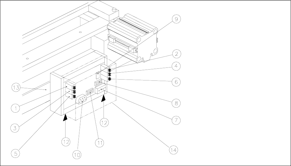
14.1.11 Exchanging the Control Unit
Fig. 14.1.9 Exchanging the Control Unit (Controller Board Assembly), Allocation of the Plug-and-Socket Connections
Key:
1) Drive of solenoid valve for cylinder 2 (left) 2) Drive of solenoid valve for cylinder 1 (right)
3) to the proximity switch on cylinder 2, FRONT 4) to the proximity switch on cylinder 1, FRONT
5) to the proximity switch on cylinder 2, BACK 6) to the proximity switch on cylinder 1, BACK
7) Cutter power supply 8) Drive of cutter
9) Service plug (only for Siemens service engineers) 10) CAN bus (only busy on HS-50 machines)
11) Coding plug (only busy on HS-50 machines 12) Spring-mounted elements to disconnect the
control box
13) Support bar 14) Cover
The cutter remains installed in the machine.
● Move the appropriate changeover table out of the machine or (in case of F4/F5) dismantle the component
table next to the WPC where applicable and remove the component table.
Service Manual SIPLACE 80S-20/F4/F5 14 Pneumatic Cutter
Edition 04/98 14.1 Pneumatic Cutter and Empty-Tape Duct
14 - 18
● Remove the cover from the controller board (see Fig. 14.1.9 -> 14).
● Disconnect all plug-and-socket connections of the controller board (see Fig. 14.1.9).
● Disconnect the control unit (box) off from the support bar by pushing both of the spring-mounted elements
away from the bar (see Fig. 14.1.9 -> 12).
● Install the new control unit (item no.: see Section 14.1.2) correctly rotated and positioned on the bar and
engage the unit.
● Restore all plug-and-socket connections in the correct allocation.
● Place the
FRYHU
back on the controller board.
● Make certain that the plug-and-socket connections are not subjected to tensile stress (see Fig. 14.1.10
-> 8).
● Perform the “Final Steps” (see Section 14.1.17).
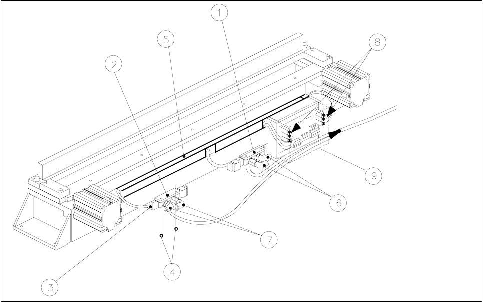
14.1.12 Exchanging the Solenoid Valve on Left or Right (and/or Cable)
Fig. 14.1.10 Exchanging the Solenoid Valve
Key:
1) Solenoid valve for cyinder 1, 2) Solenoid valve for cylinder 2,
incl. mounting plate incl. mounting plate
3) Plug-and-socket connection 4) Fastening for solenoid valve: 2 socket hex bolts each, M3 x 6
5) Cable pit cover 6) Compressed air hose for cylinder 1
7) Compressed air hose for cylinder 2 8) Cable/plug-and-socket connections: strain relief device
9) Cover
14 Pneumatic Cutter Service Manual SIPLACE 80S-20/F4/F5
14.1 Pneumatic Cutter and Empty-Tape Duct Edition 04/98
14 - 19
The cutter
UHPDLQVLQVWDOOHG
in the machine.
● Move the appropriate changeover table out of the machine or (in case of F4/F5) dismantle the component
table next to the WPC and remove the component table.
● ,IWKHFDEOHRIWKHVROHQRLGYDOYHLVIDXOW\
● Remove the cover from the control board (see Fig. 14.1.9 -> 14).
● Unplug the plug-and-socket connection of the faulty solenoid valve on the controller board (see Fig.
14.1.9).
● Remove the cover from the cable pit (see Fig. 14.1.9).
● Take out the cable and lay new the cable from the tape cutter to the valve (item no.: see Section
14.1.2).
● Make the
SOXJDQGVRFNHWFRQQHFWLRQ
on the board (see Fig. 14.1.9) and on the solenoid valve..
● Place the
FRYHU
back on the controller board.
● Install the cable pit cover and make certain there is no
WHQVLOHVWUHVV
on the plug-and-socket connec-
tions (see Fig. 14.1.10 -> 8).
● ,IWKHVROHQRLGYDOYHLVIDXOW\
● Undo the 2 compressed air connections on the solenoid valve.
● Undo the bolts fastening the solenoid valve (2 M3 bolts: see Fig. 14.1.10 -> 4) and remove the sole-
noid valve.
● Mount the new solenoid valve (item no.: see Section 14.1.2) in the correct position, as shown in Fig.
14.1.10.
-> The cable must feature a
WHQVLOHVWUHVVUHOLHIGHYLFH
(see Fig. 14.1.10 -> 8).
● Mount the short-stroke cylinder
FRPSUHVVHGDLUFRQQHFWLRQV
to the solenoid valve with the
FRUUHFW
DOORFDWLRQ
(see Fig. 14.1.7 -> 8).
● Perform the “Final Steps” (see Section 14.1.17).
14.1.13 Exchanging the Inductive Proximity Switch
The cutter remains installed in the machine.
● Move the appropriate changeover table out of the machine or (in case of F4/F5) dismantle the component
table next to the WPC and remove the component table.
● Remove the cover from the control board (see Fig. 14.1.9 -> 14).
● Disengage the plug-and-socket connection of the faulty proximity switch on the controller board (allocation:
see Fig. 14.1.9) and remove the cover from the cable pit (see Fig. 14.1.10 -> 5).
● Undo the bolt fastening the proximity switch on the short-stroke switch (1 bolt: see Fig. 14.1.7 -> 4 or 5)
and remove the proximity switch including the cable.
● Install the new proximity switch (item no.: see Section 14.1.2), ay the cable and restore the SOXJDQG
VRNNHWFRQQHFWLRQ
-> 0DNHFHUWDLQ there is QR WHQVLOHVWUHVVon the plug-and-socket connections (see Fig. 14.1.10 -> 8).
● Place the FRYHU back on the controller board.