F5 SERVICE MAUNAL.pdf - 第192页
6 PCB Handling SIPLACE 80S-20/F4 Service Manual 6.7 Lifting Table Edition 01/96 6 - 36 6.7.5 Replacing the lifting table limit switches Spare parts, auxili ary materials and equipment Lifting t able lim it switch , Item …

SIPLACE 80S-20/F4 Service Manual 6 PCB Handling
Edition 01/96 6.7 Lifting Table
6 - 35
6.7.3.2 Fitting the lifting table motor
Fit the lifting table motor in the reverse sequence of operations to removing it.
NOTE O
With the aid of the circuit diagrams folder make sure that the colored wires of the power cable are connected
to the correct terminals in the terminal strip of the ’Lifting table stepping motor A7’ conversion unit.
● Install the lifting table plate as described in Section 6.7.2, Page 6 - 32.
6.7.3.3 Function test
Carry out setting and function testing with the aid of the adjustment instructions.
6.7.4 Replacing the toothed belt
Spare parts, auxiliary materials and equipment
Synchroflex toothed belt 16T5/455, Item No. 00317782-01
SITEST program
NOTE OOO
You should also comply with the safety instructions in Chapter 1 and Section 6.7.1, Page 6 - 31.
● Remove the lifting table as described in Section 6.7.1, Page 6 - 31.
● Remove the drive base plate as described in Section 6.7.3, Page 6 - 34.
● Slacken off the M6 hexagon socket screws of the lifting table motor.
● Replace the toothed belt (see Fig. 6.7.3, Page 6 - 34).
● Tighten up the mounting screws of the lifting table motor again.
● Attach the drive base plate.
● Install the lifting table plate as described in Section 6.7.2, Page 6 - 32.
● Carry out setting and function testing with the aid of the adjustment instructions.
6 PCB Handling SIPLACE 80S-20/F4 Service Manual
6.7 Lifting Table Edition 01/96
6 - 36
6.7.5 Replacing the lifting table limit switches
Spare parts, auxiliary materials and equipment
Lifting table limit switch, Item No. 00317892-03
NOTE OOO
You should also comply with the safety instructions in Chapter 1 and Section 6.7.1, Page 6 - 31.
● Remove the lifting table as described in Section 6.7.1, Page 6 - 31.
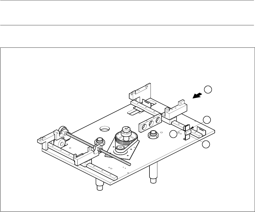
Fig. 6.7.4 Replacing the lifting table limit switch
Key to Fig. 6.7.4
● Use a pin to mark the precise position of the limit switch as installed (A).
● Unsolder the connection wires.
● Remove the limit switch and fit the new one at the place marked.
● Solder the connection wires on.
● Install the lifting table as described in Section 6.7.2, Page 6 - 32.
1 ’Lifting table at bottom’ limit switch 2 ’Lifting table at top’ limit switch
T Direction of board transport
1
2
A
T
SIPLACE 80S-20/F4 Service Manual 6 PCB Handling
Edition 01/96 6.8 Width Adjustment
6 - 37
6.8 Width Adjustment
6.8.1 Replacing toothed belts
Spare parts, auxiliary materials and equipment
Synchroflex toothed belt 10T2.5/230, Item No. 00317711-01
SITEST program
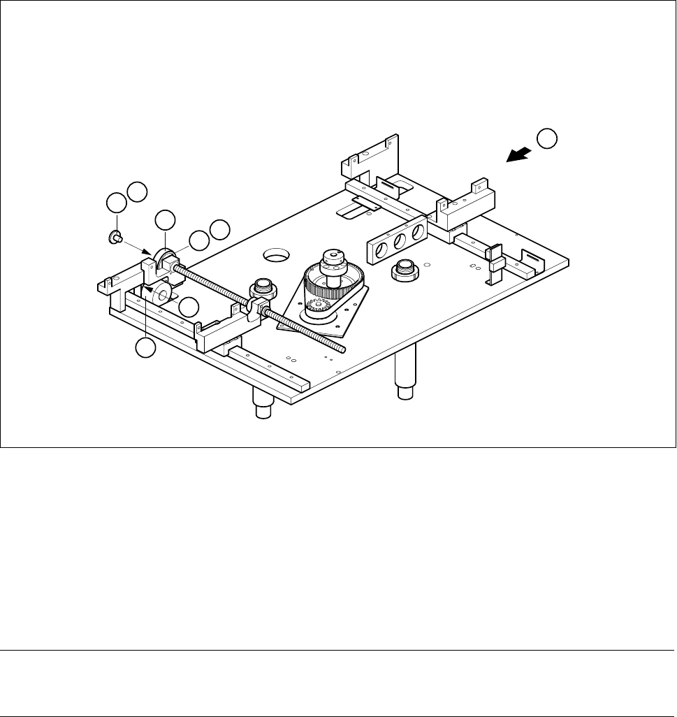
Fig. 6.8.1 Width adjustment
Key to Fig. 6.8.1
NOTE OOO
You should also comply with the safety instructions in Chapter 1 and Section 6.7.1, Page 6 - 31.
● Remove the lifting table as described in Section 6.7.1, Page 6 - 31.
● Undo the three M3 x 6 countersunk screws which fasten the pressure flange (A) to the synchronizing disk.
1 Synchroflex toothed belt 10T2.5/230 2 Synchronizing disk 2 Al T2.5/Z64
3 Width adjustment stepping motor 4 Pressure flange
T Direction of board transport
1
2
T
B
3
C
4
A