F5 SERVICE MAUNAL.pdf - 第473页
14 Pneumatic Cutter Service Manual SIPLACE 80S- 20/F4/F5 14.1 Pneumatic Cutter and Empty-Tape Duct Edition 04/98 14 - 15 Fig. 14.1.8 Removing Articulated joint from t he Cylinder, Install ing It on New Master Cylinder an…
Service Manual SIPLACE 80S-20/F4/F5 14 Pneumatic Cutter
Edition 04/98 14.1 Pneumatic Cutter and Empty-Tape Duct
14 - 14
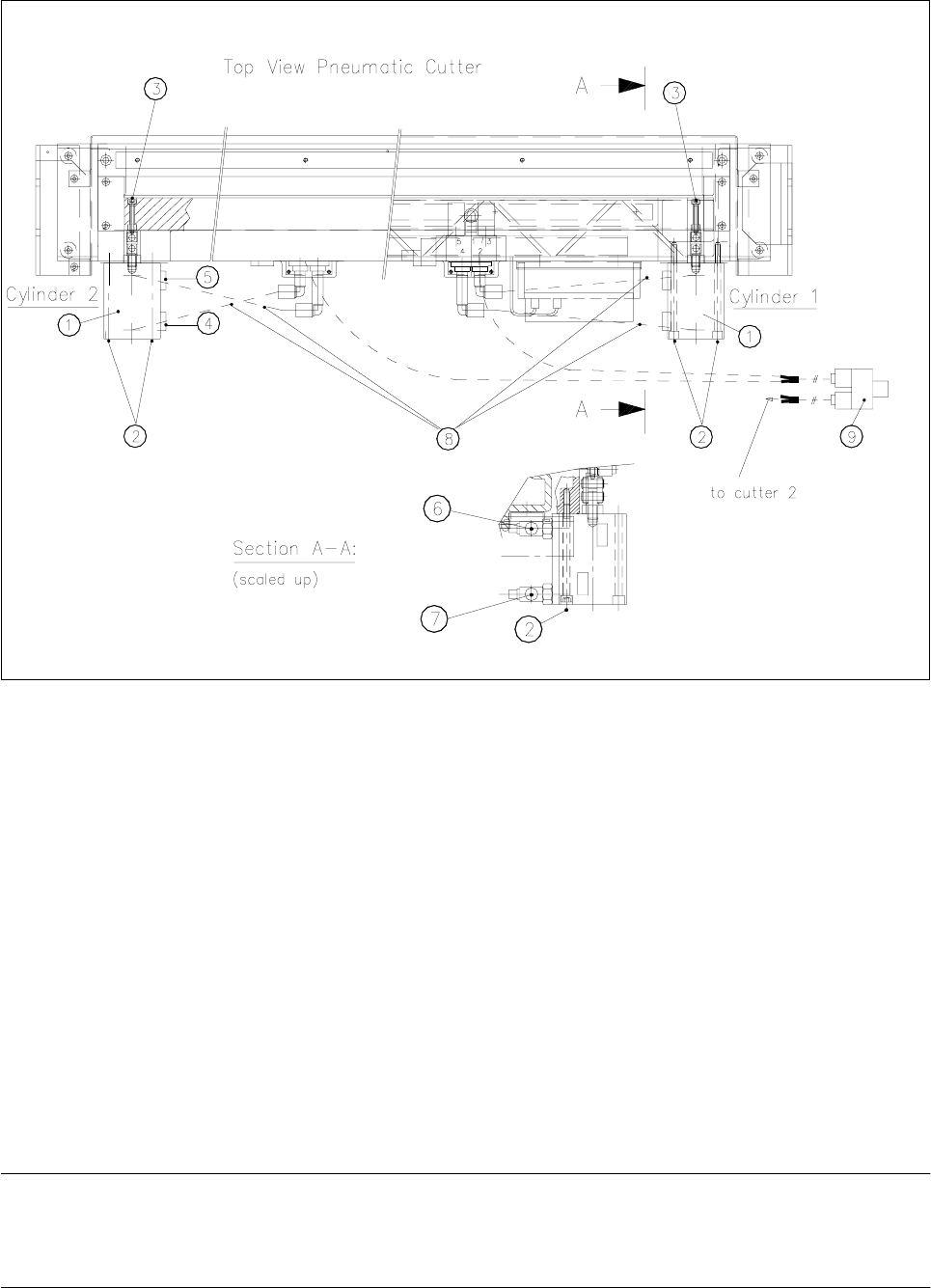
Fig. 14.1.7 Removing and Installing the Short-Stroke Cylinder
.H\
1) Short-stroke cylinders 1 and 2 2) Fastening the short-stroke cylinders
2 socket hex bolts each, M5 x 75
3) Fastening the articulated joint (see also Fig. 14.1.5) 4) Proximity switch (run
LQ
for cylinder)
Fastening: 1 cross-slotted bolt
5) Proximity switch (run
RXW
for position) 6) One-way restrictor (run
RXW
for cylinder)
Fastening: 1 cross-slotted bolt
7) Drosselrückschlagventil (für Zylinder einfahren)
8) Allocation of the compressed air connections, 9) Y-socket union (compressed air 5 bar compressed
air hoses from safety valve)
● Dismantle articulated joint from the cylinder by turning the open-end wrench (width across flats 10) on the
surface indicated in Fig. 14.1.8 -> 3.
NOTE
The threaded pin is secured with Loctite no. 243, so it takes somewhat more strength to loosen it. If neces-
sary, warm the area where it is screwed in until the articulated joint can be loosened.
14 Pneumatic Cutter Service Manual SIPLACE 80S-20/F4/F5
14.1 Pneumatic Cutter and Empty-Tape Duct Edition 04/98
14 - 15
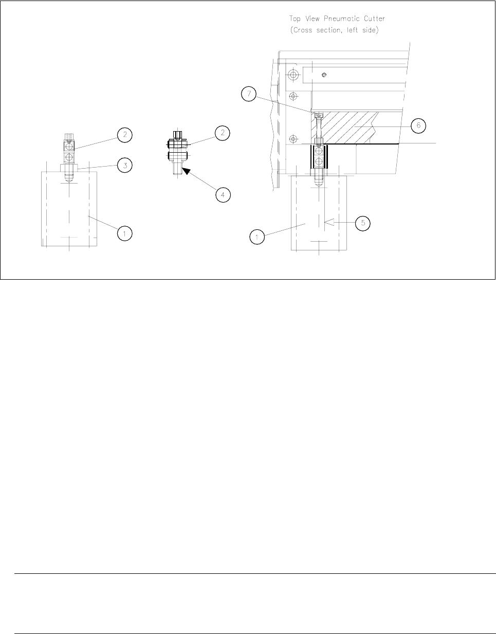
Fig. 14.1.8 Removing Articulated joint from the Cylinder, Installing It on New Master Cylinder and Bonding It in Place
Key:
1) Short-stroke cylinder (1 or 2) 2) Articulated joint (complete)
3) Wrench surface for disassembling the 4) Secure articulated joint thread with Loctite no. 243
articulated joint
5) Open-end wrench surface of articulated joint 6) Friction surface of the movable blad
7) Fastening the articulated joint (see also Fig. 14.1.5)
● Clean the residues of Loctite from thread of articulated joint pin and apply a small amount of Loctite no.
243 (item no.: see Section 14.1.3) to the thread.
● Screw the threaded pin into the new short-stroke cylinder (item no.: see Section 14.1.2).
Turn the articulated joint into the mounting position (see Fig. 14.1.8, diagram on left) and tighten the
articulated joint against the wrench surface.
● Disassemble the one-way restrictors from the faulty cylinder and screw them in correctly allocated for
“move in/move out” on the new cylinder (open-end wrench, size 14).
-> Afterwards, check and, if necessary, correct the setting of the one-way restrictors.
● Remount the prepared cylinder on the cutter (2 bolts: see Fig. 14.1.7).
HINWEIS
Make certain that the lateral surface / open-end wrench surface of the articulated joint (see Fig. 14.1.8
-> 5) is DWULJKWDQJOHWRWKHIULFWLRQVXUIDFHof the movable wrench ( -> 6).
● Fasten the cylinder in this position with the 2 bolts each (see Fig. 14.1.7 -> 2).
● Remount the 2 proximity switches in the FRUUHFWDOORFDWLRQ(position: front/back on the cylinder (see Fig.
14.1.7 -> 4, 5).
-> As the final step, the switching points must be adjusted (see Section 14.1.13).

Service Manual SIPLACE 80S-20/F4/F5 14 Pneumatic Cutter
Edition 04/98 14.1 Pneumatic Cutter and Empty-Tape Duct
14 - 16
● Connect the compressed air hoses to the cylinder in the correct allocation (threaded quick-action
release). Allocation: see Fig. 14.1.7.
● Insert the cover plate back in from above (see Fig. 14.1.4 -> 4) and bolt it tight (see Fig. 14.1.5 -> 9).
● Install the empty-tape channel (2 bolts: see Fig. 14.1.1 -> 9).
NOTE
To bring the installation height into correspondence the spacer disks must be placed under the pins as
before (see Fig. 14.1.1 -> 10). Checking the correspondence: see Section 14.1.14.
● Adjust the switching points of the proximity switches as described in Section 14.1.13.
● Check and correct the setting of the one-way restrictors as described in Section 14.1.10.
● Perform the appropriate “Final Steps” (see Section 14.1.17).
14.1.10 Setting/Exchanging the One-way restrictors to “Move Cylinder
In/Out”
DANGER O O O
6
trictly adhere to the instructions in the DANGER text in Section 14.1.1.
There is a high risk of accidents when working with the SITEST program.
The cutter remains installed in the machine.
● Move the appropriate changeover table out of the machine or (in case of F4/F5) dismantle the component
table next to the WPC, where applicable, and dismantle the component table.
● Load the SITEST program and start the cutting strokes (see operating manual for SITEST program). In the
process, check whether the
WLPLQJRIWKHWZRF\OLQGHUV
while moving in and out corresponds to the
GLD
JUDPLQ
Section 14.1.6.
● If there is a
QRWLFHDEOHGLIIHUHQFH
correct the setting of the one-way restrictors (see Fig. 14.1.7):
- Deviations
FDQEH
FRUUHFWHG
by changing the setting:
● As the final step, apply Loctite no. 454 (item no.: see Section 14.1.3) to the RQHZD\UHVWULFWRUV
in the set position.
● Exit the SITEST program, turn the key-operated switch to the normal position and lock up the key.
- Deviation FDQQRWEHFRUUHFWHGby changing the setting:
● Exit the SITEST program, turn the key-operated switch to the normal position and lock up the key.
● For the following check, turn the machine off, disconnect the machine from the mains and turn the
compressed air off at the input of the compressed air unit (see DANGER text in Section 14.1.1).
● First make sure there is no interruption of the compressed air supply (e.g., a leaky connection or
a kink in the compressed hose).