F5 SERVICE MAUNAL.pdf - 第144页
5 Gantries SIPLACE 80S-20/F4/F4-6/F5 Service Manual 5.7 Exchanging the X -/Y-Trailing Cable Edition 09/99 5 - 36 Fig. 5.7.15 Loosening the C ounterstay (X-Cable Clamp) for X-Trailing Cable, Unplugging Ribbon Cable from B…
SIPLACE 80S-20/F4/F4-6/F5 Service Manual 5 Gantries
Edition 09/99 5.7 Exchanging the X-/Y-Trailing Cable
5 - 35
5.7.6.6 X-Gantry Area: Dismantling the Ribbon Cables and/or Pneumatic Hoses
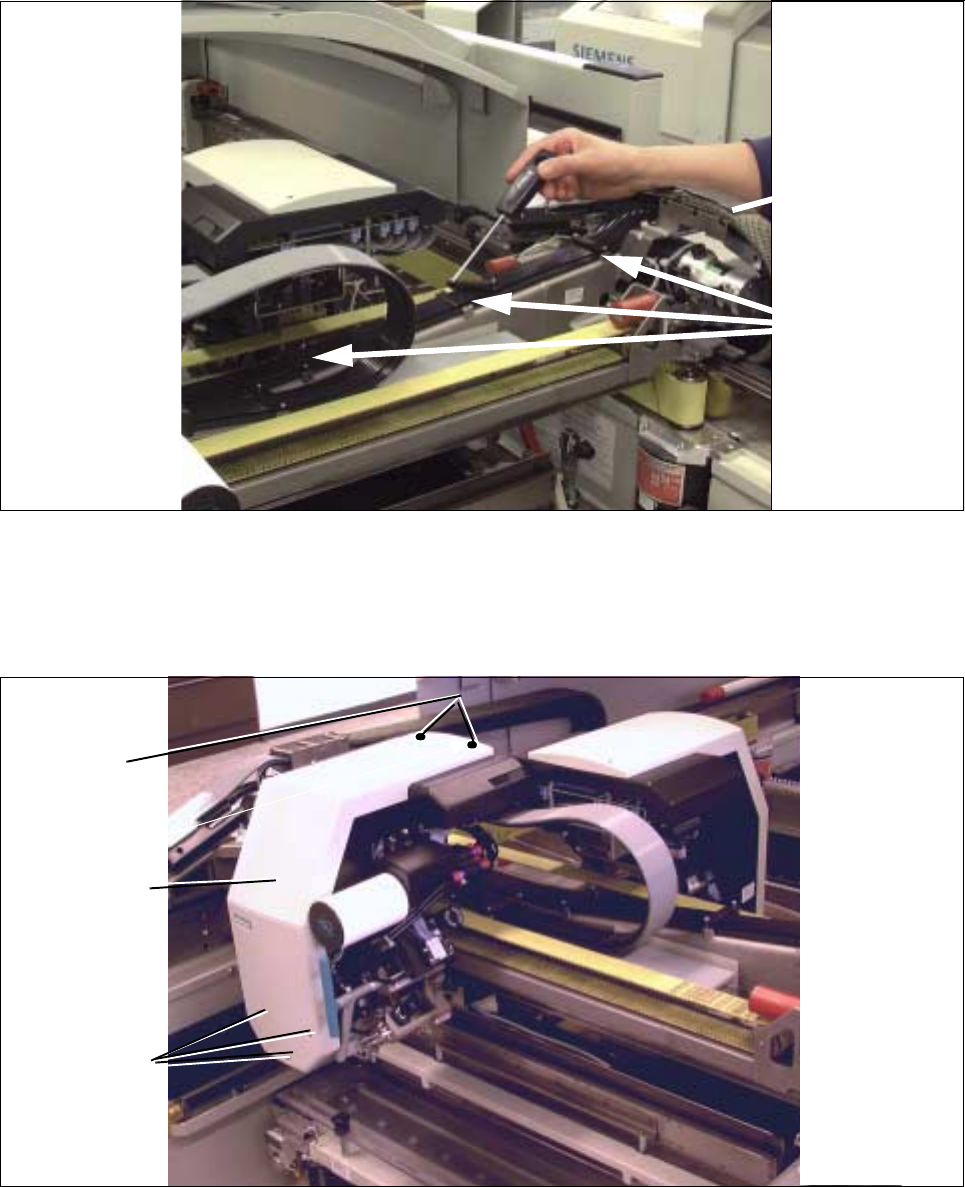
Fig. 5.7.13 Loosening the Three Retaining Blocks (Holddown) Along the X-Axis
● Remove the 3 holddowns from the X-axis (loosen two M3 socket hex cap screws holding each: see Fig.
5.7.13). Put down all of the components including the screws outside the X-gantry area, e.g. on the cover
of the input unit.
Fig. 5.7.14 Removing the Cover of the Pertinent Revolver Head
● Comply with the regulations on ESDs (see WARNING below):
Dismantle the cover from the revolver head (4 or 5 screws, depending on the model; size 2.5 Allen wrench:
see Fig. 5.7.14). In the case of the S-20, it is dismantled from the pertinent revolver head.
3 holddowns for
X-trailing cable
Y-trailing cable
(dismantled)
Two M 2
Three M 3
Cover for
revolver head
M2
screws
5 Gantries SIPLACE 80S-20/F4/F4-6/F5 Service Manual
5.7 Exchanging the X-/Y-Trailing Cable Edition 09/99
5 - 36
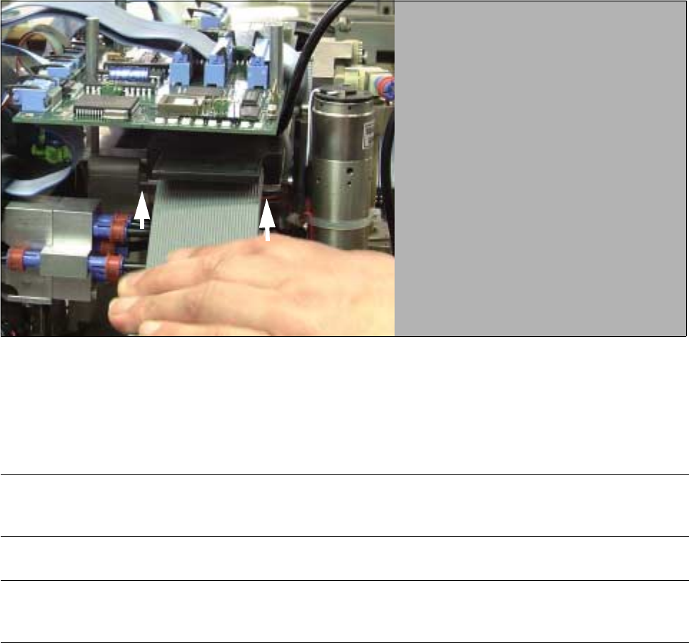
Fig. 5.7.15 Loosening the Counterstay (X-Cable Clamp) for X-Trailing Cable, Unplugging Ribbon Cable from Board
● Loosen the counterstay of the X-trailing cable under the “Small Axis” conversion board (loosen 2 screws
from the bottom, size 2.5 Allen wrench: see Fig. 5.7.15).
l Loosen plug-in connectors on the “Small Axis” conversion board (head board):
WARNING O O
Comply with regulations on ESDs (see Section 1 of this service manual.
NOTE
If only the 7-tube pneumatic hose is exchanged, skip the next 3 steps.
● Loosen the fasteners or the “Small Axis” conversion board at the studs (3 screws, size 2.5 Allen
wrench: see Fig. 5.7.2).
● Carefully tip the side of the board up and carefully pull all of the plug-in connectors of the X-trailing
cable off the bottom of the board.
● As a precautionary measure, fasten the board with at least one screw in the interim.
SIPLACE 80S-20/F4/F4-6/F5 Service Manual 5 Gantries
Edition 09/99 5.7 Exchanging the X-/Y-Trailing Cable
5 - 37
● Loosening the pneumatic connections in the placement head area:
Fig. 5.7.16 S-20 and F4/F5: Loosening Pneumatic Connections on the Revolver Head (or Reconnecting and Laying Them Correctly)
● S-20 and F5/F5: Loosen the 5 compressed air connections on the distributor block of the revolver
head (move red ring of quick-release fastener: see Fig. 5.7.16 -> 1).
On S-20, hoses 1 and 2 are not under pressure. For this reason they are run down the side of the
revolver head (see top right -> 2) and inserted behind the cross member (-> 3).
Loosen the 2 cable ties.
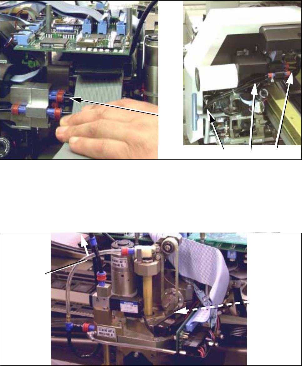
Fig. 5.7.17 F4/F5: Loosening the Pneumatic Connections on the IC Head (or Reconnecting Them Correctly)
● F4/F5: In addition to the connections on the revolver head (see Fig. 5.7.17), loosen the compressed
air connections on the IC head:
- 5.5 bar on the vacuum generator (Y-coupling: see Fig. 5.7.17) and
- 2.3 bar at solenoid valve for the Z-axis clamping unit (quick-release fastener: see Fig. 5.7.17).
1
F4 / F5
3
2
1
S-20
1
S-20
Connection to
pneumatic
system
2,3 bar
Connection to
pneumatic
vacuum
5,5 bar
system for
generator
(Y-connector)
for Z-axis
clamping unit