F5 SERVICE MAUNAL.pdf - 第292页
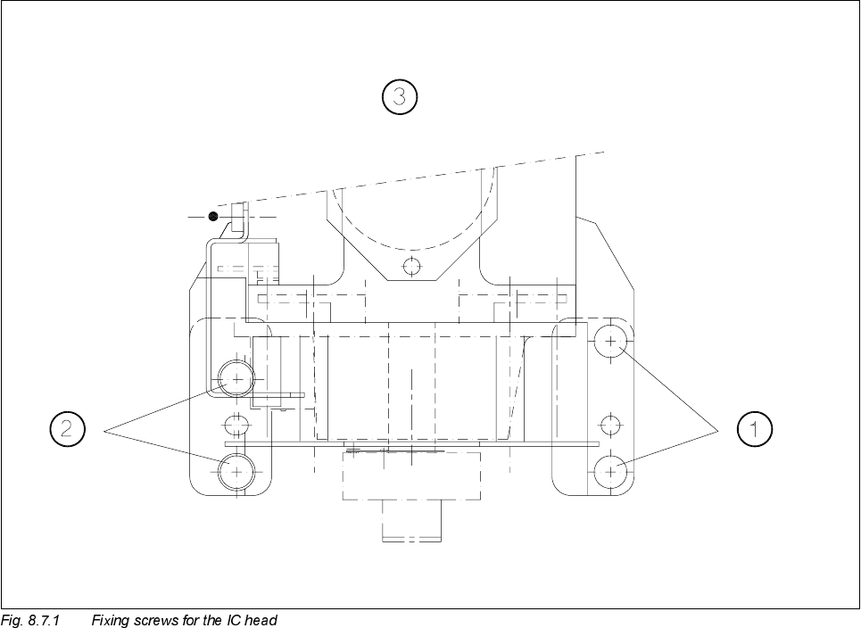
8 IC Head S IPLACE 80S-20/F4 Service Manual 8.7 Disassemble and Reassemble IC Head Edition 01/97 8 - 30 Key to Fig. 8.7.1 . 1 Fil liste r head s crew M4 x 25 2 Filliste r head screw M 4 x 16 3 Viewed in the pla cement he…

SIPLACE 80S-20/F4 Service Manual 8 IC Head
Edition 01/97 8.7 Disassemble and Reassemble IC Head
8 - 29
'LVDVVHPEOHDQG5HDVVHPEOH,&+HDG
7RROV(TXLSPHQW
6SDUH3DUWV
'LVDVVHPEOHWKH,&+HDG
● Detach all power cables and air hoses.
● Loosen the four fixing screws for the IC head as shown in Fig. 8.7.1.
● Remove the IC head and fix it to the mounting rack for the IC head.
)LWWKH,&+HDG
● Fix the IC head in place using the 4 fixing screws. Please note that the screws are of different lengths! (see
Fig. 8.7.1 page 8 - 30)
● Attach the power cables to the IC head board (see Fig. 8.2.2 page 8 - 8).
● Reconnect the air hoses.
● Edit the zero point correction values for the z and dr axes in the MA data.
● Check the dynamic performance of the servo axes with reference to the Adjusting Instructions and adjust
the axes.
● Measure the automatic placement machines with reference to the IC head.
)URPLWHPQXPEHU
Slotted head screw driver, set
Mounting rack for the IC head 00318295-01
SITEST program V ≥ 203.000
Test box
Adjusting Instructions
)URPLWHPQXPEHU
IC head for CAN bus 00322583S01
SIPLACE 80S-20/F4 Service Manual 8 IC Head
Edition 01/97 8.8 Servicing work that can only be carried out at the factory
8 - 31
6HUYLFLQJZRUNWKDWFDQRQO\EHFDUULHGRXWDWWKH
IDFWRU\
● Servicing work on the z axis clamping device
This does not include replacement of the solenoid valve
● Servicing work on the dr axis encoder unit
● Removal of the head housing cover plate
❒