F5 SERVICE MAUNAL.pdf - 第199页
SIPLACE 80S-20/F4 Service Manual 6 PCB Handling Edition 01/96 6.9 Sonar BERO 6 - 43 6.9.3 Adjustment and function test ● Lift the liftin g table pl ate a l ittle and h old the pl ate at th is heigh t with th e aid of th …
6 PCB Handling SIPLACE 80S-20/F4 Service Manual
6.9 Sonar BERO Edition 01/96
6 - 42
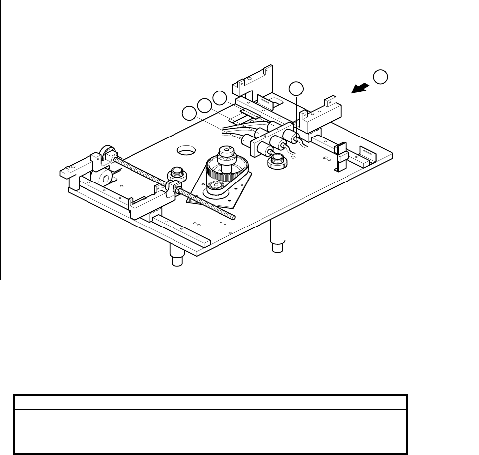
● Undo the clamp holding the sonar BERO (B).
● Disconnect the sensing head cable from the evaluation unit (C).
Fig. 6.9.2 Removing the sonar BERO evaluation unit
Key to Fig. 6.9.2
● Disconnect the connection cables of the evaluation units from the terminals of conversion unit II ’BEROS’,
A3, A4:
● Remove the sensing head and the evaluation unit.
6.9.2 Fitting the sonar BERO unit
● Fit the new BERO unit.
● With the aid of the circuit diagrams folder make sure that you have connected the unit up properly.
● Install the lifting table as described in Section 6.7.2, Page 6 - 32.
1 Output conveyor sonar BERO evaluation unit 2 Input conveyor sonar BERO evaluation unit
3 Center conveyor sonar BERO evaluation unit
Sonar BERO Terminal strip X1rp, terminals Cable
Input conveyor 1, 6, 15 Y461-W1
Center conveyor 2, 7, 16 Y462-W1
Output conveyor 3, 8, 17 Y463-W1
T
C
3
2
1
SIPLACE 80S-20/F4 Service Manual 6 PCB Handling
Edition 01/96 6.9 Sonar BERO
6 - 43
6.9.3 Adjustment and function test
● Lift the lifting table plate a little and hold the plate at this height with the aid of the board support.
● Switch the machine on and press the EMERGENCY STOP button.
● With the aid of the adjustment instructions carry out the required adjustments followed by a function test.
6 PCB Handling SIPLACE 80S-20/F4 Service Manual
6.9 Sonar BERO Edition 01/96
6 - 44