F5 SERVICE MAUNAL.pdf - 第154页
5 Gantries SIPLACE 80S-20/F4/F4-6/F5 Service Manual 5.7 Exchanging the X -/Y-Trailing Cable Edition 09/99 5 - 46 5.7.8 Final St eps ● Insta ll the co ver ov er the revolv er head ( 4 or 5 s crews, siz e 2 Allen wrench: s…
SIPLACE 80S-20/F4/F4-6/F5 Service Manual 5 Gantries
Edition 09/99 5.7 Exchanging the X-/Y-Trailing Cable
5 - 45
● If the protective hose is too long, move the bottom end of the ribbon cable until the end of the hose
that is to be cut off is safely outside
the machine.
By doing so you ensure that no fabric fibers end up in the machine area during the subsequent
steps. Cut off the protective hose smooth and at right angles with sharp scissors. The end of the pro-
tective hose should not protrude over the Y-strain relief device.
● If the criteria in the above-mentioned NOTE are not observed, proceed as follows:
- If there is a space at the loop of the cable supply chain, loosen the fasteners on the Y-trailing
cable hanger again, pull the trailing cable on the protective hose up slightly and refasten it in that
position (see above).
- If the protective hose is pressing against the loop of the cable supply chain / touching too much,
try changing the position of the cable supply chain’s bottom U-bracket in the slots. If this does not
suffice, remove the Y-strain relief device again and move the trailing cable (protective hose with
contents)
an appropriate amount and put the reversing pin back in. Tighten the screws holding the Y-strain
relief device.
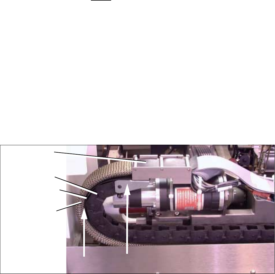
● Manually push the Y-gantry into the min. and max. travel position. In each case, make certain that the
above condition is fulfilled (see Fig. 5.7.21 -> Check 2 !).
Fig. 5.7.21 Resetting and Checking the Correct Distance from “Protective Hose to Cable Supply Chain”,
Checking the correct assembly of U-bracket (Example for F4/F5)
● Attach the plug-in connector of the 2 ribbon cables on the top to the “Large Axis” conversion board. Check
to ensure that the plug-in connectors are securely seated.
● Install the cover over the “Large Axis” conversion board (3 screws, size 2 Allen wrench). Perform the
"Final Steps".
Y-trailing cable
completely
Cable supply chain
bolted in placet
Cover band
inserted
Protective hose
Check 2 !
assembled
Check 1 !
5 Gantries SIPLACE 80S-20/F4/F4-6/F5 Service Manual
5.7 Exchanging the X-/Y-Trailing Cable Edition 09/99
5 - 46
5.7.8 Final Steps
● Install the cover over the revolver head (4 or 5 screws, size 2 Allen wrench: see Fig. 5.7.14).
● Carry out a visual inspection:
- Is the cable supply chain mounted correct (wide U-bracket must be at top, see Fig. 5.7.21 ->
Check 1 !) ?
- Is the bend an the transition from Y-gantry to the X-gantry properly executed (see Fig. 5.7.20) ?
- Is the cover band between the cable supply chain and the protective hose ?
- Is the protective hose over the outer radius of the cable supply chain neither too loose nor too
tight ?
- Are the “Y-strain relief device" and the cable train hanger (Y-axis) installed exactly parallel to the Y-
gantry rail ?
- Are the pneumatic hoses correctly allocated on the placement head and connected to the air dis-
tributor next to the Y-gantry ?
- Is the ribbon cable allocation to the connectors of the gantry board correct ?
Compare the ID markings on the cables and the board.
● Place the side guard next to the machine and plug the cable lug of the grounding cable onto the connec-
tor on the inside (see Fig. 5.7.5 -> 8).
● Install the side guard, initially attaching it with the four M6 screws that are one under the other (Size 5 Allen
wrench, see Fig. 5.7.5).
● Install the protective door on the component feeding and fasten it with the 2 remainig screws M6 on the
front of the side guard.
● Place the machine base doors into their hinges.
● Place the buffer bracket onto the centering pins and bolt the bracket on (1 screw, size 6 Allen wrench: see
Fig. 5.7.1 -> 8).
● Bolt on the cover plate above the side guard (4 - 5 screws, size 3 Allen wrench: see Fig. 5.7.5).
● Move the component changeover table/carriage back into the machine or, in the case of the F4/F5, put the
exchangeable (stationary) component table back in.
● Set up the stationary component in accordance with the specifications for set-up optimization.
● Where applicable, move the WPC into the machine.
● Install the plug-in connectors (for power supply and interface) for the component table (1 or 2) and the
WPC.
● Conduct a visual check to ensure that all empty tape ends in the empty-tape duct are conducted down
correctly.
● Remove all tools and equipment from the machine.
● At the main switch of the machine, turn the compressed air back on at the compressed air unit.
● Start the placement sequence.
q

Service Manual SIPLACE 80S-20/F4 6 PCB Handling
Edition 03/97
6 - I
Content
Page
6 PCB Handling
6.1 Introduction . . . . . . . . . . . . . . . . . . . . . . . . . . . . . . . . . . . . . . . . . . . . . . . . . . . . . . . . . . . . . . . . . . . . . . . 3
6.1.1 Safety Instructions. . . . . . . . . . . . . . . . . . . . . . . . . . . . . . . . . . . . . . . . . . . . . . . . . . . . . . . 3
6.1.2 Tools, Auxiliary Materials and Equipment Required . . . . . . . . . . . . . . . . . . . . . . . . . . . . . 3
6.1.3 Overview of Functions. . . . . . . . . . . . . . . . . . . . . . . . . . . . . . . . . . . . . . . . . . . . . . . . . . . . 3
6.1.4 Position of the Assemblies (General Views) . . . . . . . . . . . . . . . . . . . . . . . . . . . . . . . . . . . 4
6.2 Geared Motors of the PCB Transportation Systems . . . . . . . . . . . . . . . . . . . . . . . . . . . . . . . . . . . . . . 7
6.2.1 Replacing the input and center conveyor geared motors . . . . . . . . . . . . . . . . . . . . . . . . . 7
6.2.1.1 Removing the geared motor from the input and output conveyors. . . . . . . . . . . . . . . . . 7
6.2.1.2 Fitting and testing the input and center conveyor geared motors. . . . . . . . . . . . . . . . . . 9
6.2.2 Replacing the output conveyor geared motor . . . . . . . . . . . . . . . . . . . . . . . . . . . . . . . . . . 9
6.2.2.1 Removing the geared motor from the output conveyor . . . . . . . . . . . . . . . . . . . . . . . . . 9
6.2.2.2 Fitting and testing the output conveyor geared motor . . . . . . . . . . . . . . . . . . . . . . . . . 11
6.3 Drive Units of the PCB Transportation Systems . . . . . . . . . . . . . . . . . . . . . . . . . . . . . . . . . . . . . . . . 13
6.3.1 Replacing the drive unit of the input conveyor. . . . . . . . . . . . . . . . . . . . . . . . . . . . . . . . . 13
6.3.1.1 Removing the input or output conveyor drive units . . . . . . . . . . . . . . . . . . . . . . . . . . . 13
6.3.1.2 Fitting and testing the input and output conveyor drive units . . . . . . . . . . . . . . . . . . . . 15
6.3.2 Replacing the drive unit of the center conveyor . . . . . . . . . . . . . . . . . . . . . . . . . . . . . . . 16
6.3.2.1 Removing the center conveyor drive unit. . . . . . . . . . . . . . . . . . . . . . . . . . . . . . . . . . . 16
6.3.2.2 Fitting the center conveyor drive unit . . . . . . . . . . . . . . . . . . . . . . . . . . . . . . . . . . . . . . 16
6.3.3 Replacing the output conveyor drive unit . . . . . . . . . . . . . . . . . . . . . . . . . . . . . . . . . . . . 18
6.3.3.1 Removing and installing the output conveyor drive unit. . . . . . . . . . . . . . . . . . . . . . . . 18
6.4 Conveyor Toothed Belts . . . . . . . . . . . . . . . . . . . . . . . . . . . . . . . . . . . . . . . . . . . . . . . . . . . . . . . . . . . . 19
6.4.1 Replacing the conveyor toothed belt on the fixed side of the board conveyor . . . . . . . . 19
6.4.1.1 Changing the conveyor toothed belt on the fixed side of the board conveyor . . . . . . . 19
6.4.1.2 Function Test . . . . . . . . . . . . . . . . . . . . . . . . . . . . . . . . . . . . . . . . . . . . . . . . . . . . . . . . 21
6.4.2 Replacing the conveyor toothed belt on the movable side of the board conveyor . . . . . 21
6.4.2.1 Changing the conveyor toothed belt on the movable side of the board conveyor . . . . 21
6.4.2.2 Function Test . . . . . . . . . . . . . . . . . . . . . . . . . . . . . . . . . . . . . . . . . . . . . . . . . . . . . . . . 23
6.5 Retainers and Compression Springs. . . . . . . . . . . . . . . . . . . . . . . . . . . . . . . . . . . . . . . . . . . . . . . . . . 25
6.5.1 Removing retainers and compression springs . . . . . . . . . . . . . . . . . . . . . . . . . . . . . . . . 25
6.5.2 Fitting the retainers and compression springs. . . . . . . . . . . . . . . . . . . . . . . . . . . . . . . . . 27
6.5.3 Function test . . . . . . . . . . . . . . . . . . . . . . . . . . . . . . . . . . . . . . . . . . . . . . . . . . . . . . . . . . 27