NPM-D3维修手册.pdf - 第104页
NPM-D3 SERVICE MANUAL 4.6 Optional Units Page 4-66 EJM6D3-MB-04SM-02.DOC Board Detection Sensor Layout 基板検出センサレイアウト 基板检测传感器的布局 No. Sensor name センサ名称 传感器名称 Connecto r No. コネクタ No. 连接器 No. Emission frequency 投光周期 照光周期 1 …
NPM-D3
SERVICE MANUAL
4.6 Optional Units
EJM6D3-MB-04SM-02.DOC Page 4-65
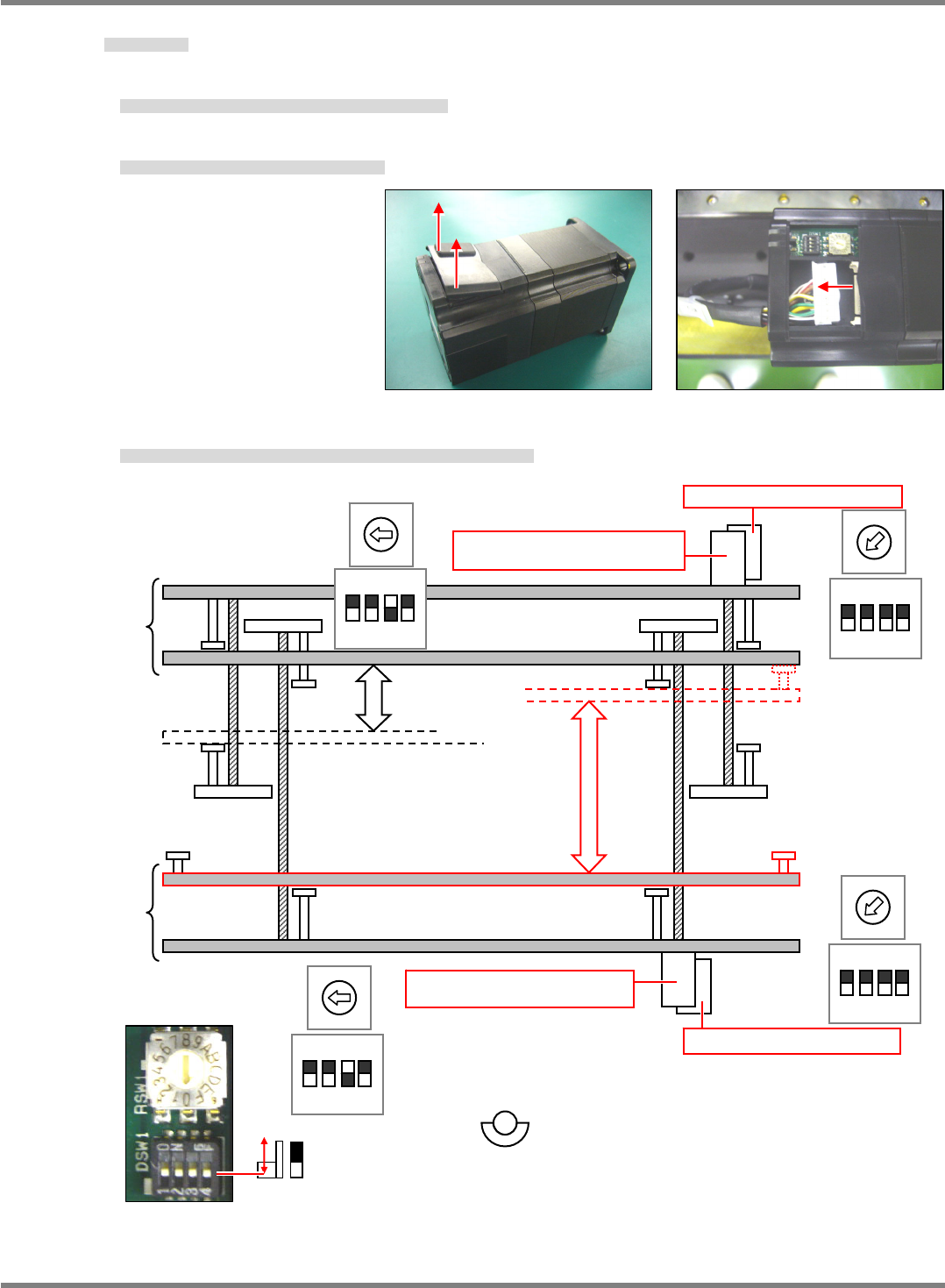
Transfer Unit Motor Replacement
搬送部モータ交換
搬送部电机的交换
9.
1. Lift the projections at the rear of the motor to open the wiring box cover. (Fig. 1)
モータ後部の突起を引き上げると配線部のカバーが開きます。(Fig. 1)
如果拉起电机后面的突起部,就打开配线部的盖。(Fig. 1)
2. Pull the connectors to disconnect the motor cables. (Fig. 2)
コネクタを引くとモータのケーブルを外せます。(Fig. 2)
如果拉起连接器,即可取下电机的电缆。(Fig. 2)
3. Set the DIP switches and rotary switch for each motor to be used. (Fig. 3)
モータの使用か所ごとに DIP スイッチとロータリースイッチの設定を行います。(Fig. 3)
在每个电机的使用位置上,进行 DIP SW 和旋转 SW 的设定。(Fig. 3)
Fig. 2 Fig. 1
Fig. 3: Factory-setting
4
Lane 2
Lane 1
M638 (Lane 2 width adjustment
motor)
M607 (Lane 1 width adjustment
moto
r
)
1234
ON
2
M602 (Lane 1 transfer motor)
M635 (Lane 2 transfer motor)
1234
ON
2
1 2 3 4
ON
4
1 2 3 4
ON
NPM-D3
SERVICE MANUAL
4.6 Optional Units
Page 4-66 EJM6D3-MB-04SM-02.DOC
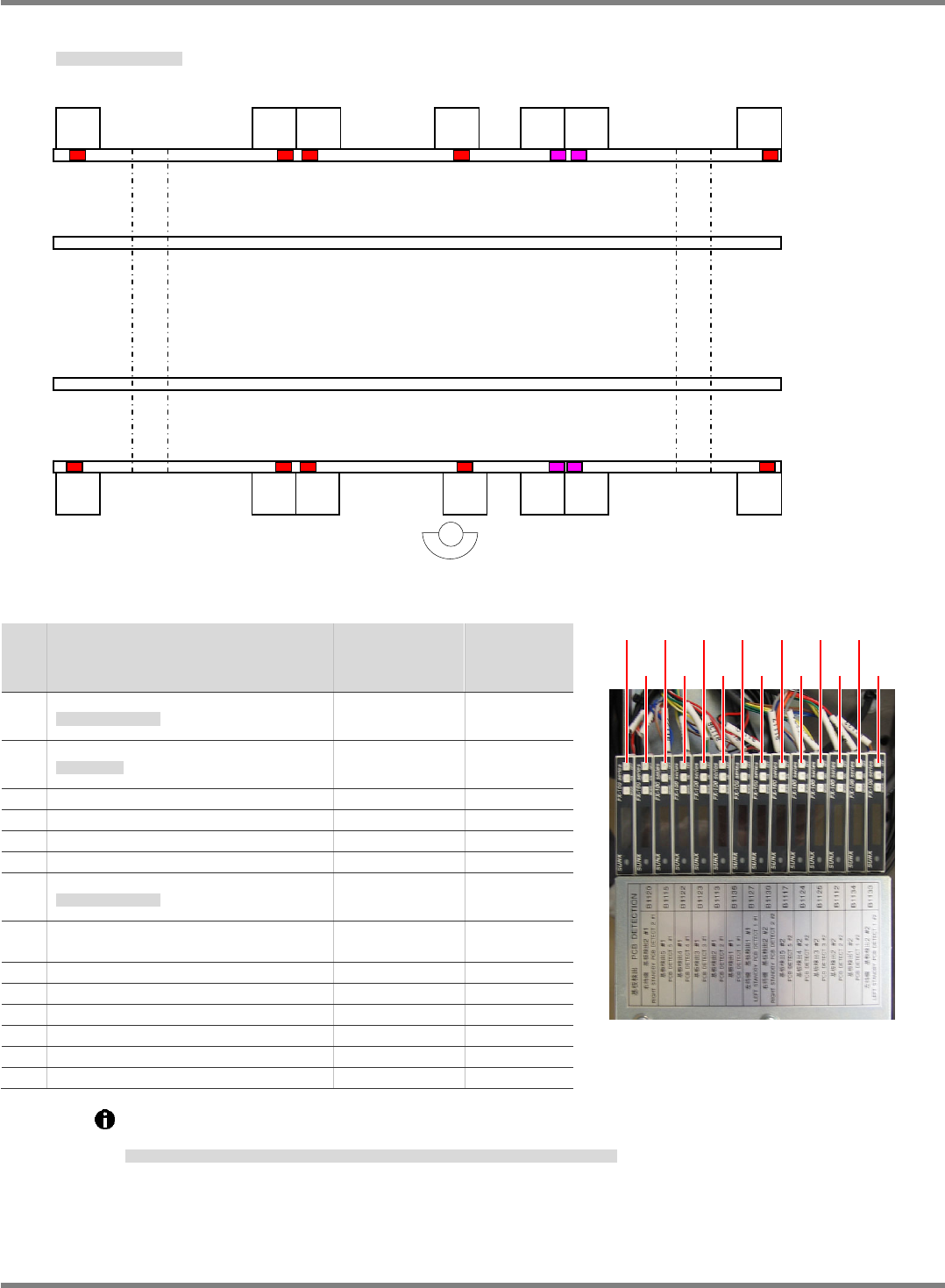
Board Detection Sensor Layout
基板検出センサレイアウト
基板检测传感器的布局
No.
Sensor name
センサ名称
传感器名称
Connector No.
コネクタ
No.
连接器
No.
Emission
frequency
投光周期
照光周期
1
Right standby board detection 2#1
右待機
基板検出
2 #1
右待机基板检测
2 #1
B1120 F0
2
Board detection 5 #1
基板検出
5 #1
基板检测
5 #1
B1115 F03
3 Board detection 4 #1 B1122 F02
4 Board detection 3 #1 B1123 F0
5 Board detection 2 #1 B1113 F02
6 Board detection 1 #1 B1136 F03
7
Left standby board detection 1 #1
左待機
基板検出
1 #1
左待机基板检测
1 #1
B1127 F0
8
Right standby board detection 2
#2
B1130 F0
9 Board detection 5 #2 B1117 F03
10 Board detection 4 #2 B1124 F02
11 Board detection 3 #2 B1125 F0
12 Board detection 2 #2 B1112 F02
13 Board detection 1 #2 B1134 F03
14 Left standby board detection 2 #2 B1133 F0
Light intensity / threshold when the rails are at origins (Rail 1: 460.5 mm / Rail 2: 216.5 mm) must
be 100 or more.
原点時のレール幅
(
レール
1 : 460.5mm /
レール
2 : 216.5mm)
における光量
/
閾値が
100
以上であること。
在原点时的轨道宽度
(
轨道
1: 460.5 mm /
轨道
2: 216.5 mm)
的光量
/
阈值应在
100
以上。
(1) (3) (5) (7) (9) (11) (13)
(2) (4) (6) (8) (10) (12) (14)
Fig. 2
(11)
R
(12)
R
(13)
R
(14)
R
(10)
R
(8)
R
(5)
T
(6)
T
(7)
T
(3)
T
(1)
T
(4)
T
(2)
T
(9)
R
Fig. 1
NPM-D3
SERVICE MANUAL
4.6 Optional Units
EJM6D3-MB-04SM-02.DOC Page 4-67
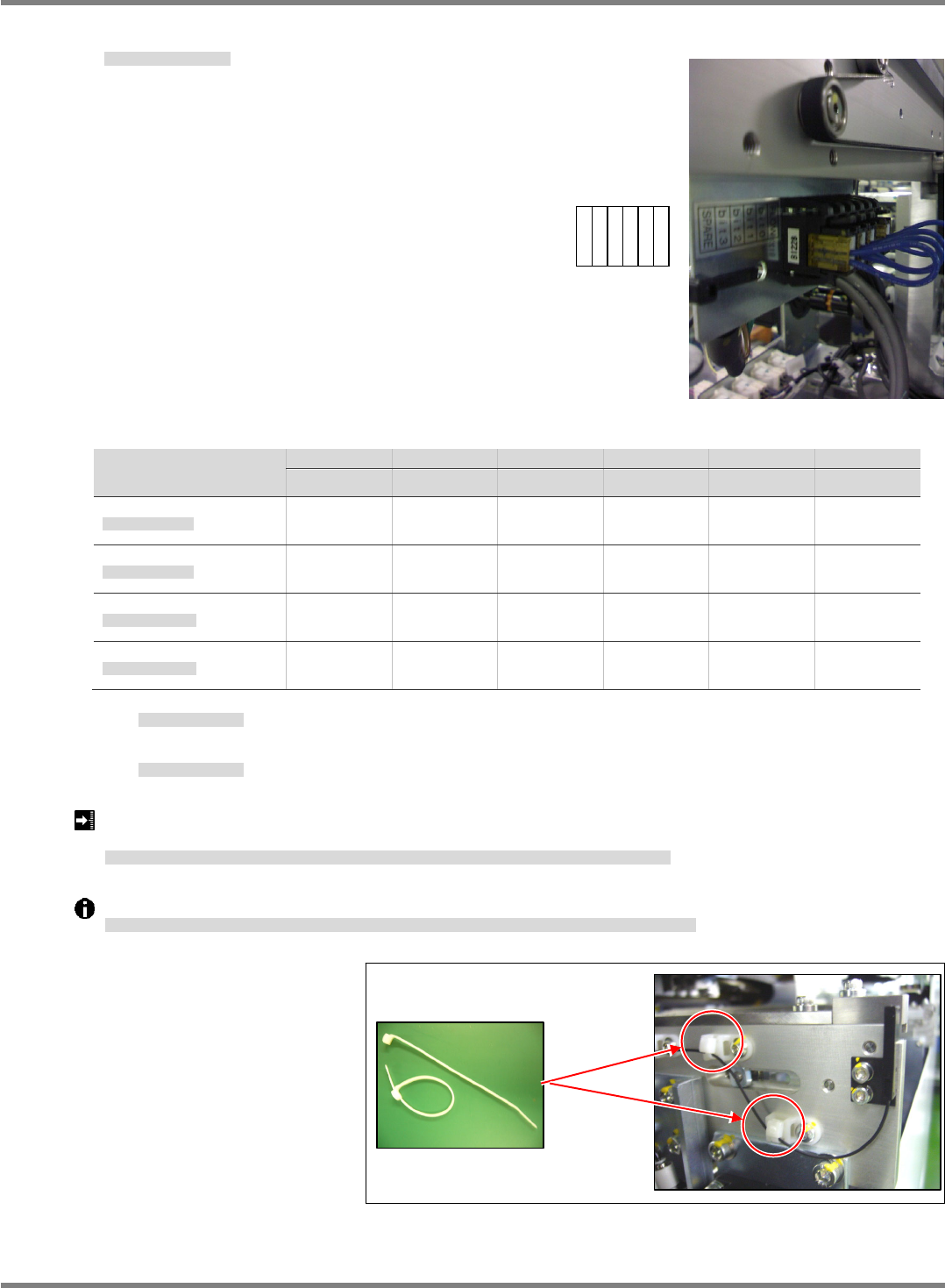
Connector Check by Transfer Specifications
搬送仕様識別コネクタ確認
搬送规格识别连接器确认
Transfer spec.
搬送仕様
搬送规格
FLOW Bit 0 Bit 1 Bit 2 Bit 3 SPARE
B1223P B1224P B1225P B1226P B1227P B1228P
PC dual normal flow
PC
デュアル正流れ
PC
双式正流向
×
○
×
○
○
○
PC dual reverse flow
PC
デュアル逆流れ
PC
双式逆流向
○
○
×
○
×
○
IPC dual normal flow
IPC
デュアル正流れ
IPC
双式正流向
×
×
○
○
○
○
IPC dual reverse flow
IPC
デュアル逆流れ
IPC
双式逆流向
○
×
○
○
×
○
○
: With short connector
ショートコネクタあり
有短的连接器
×
: Without short connector
ショートコネクタなし
无短的连接器
Light intensity / threshold when the rails are at origins (Rail 1: 460.5 mm / Rail 2: 216.5 mm) must be 100
or more.
原点時のレール幅
(
レール
1 : 320.5 mm
・
593.5 mm /
レール
2 : 320.5 mm)
における光量
/
閾値が
100
以上であること。
在原点时的轨道宽度
(
轨道
1 : 460.5 mm /
轨道
2 : 216.5 mm)
的光量
/
阈值应在
100
以上。
Dedicated cable ties are used to bundle fiber sensor cables so as not to damage the fibers. (Fig. 2)
ファイバーセンサケーブルの結束には、ファイバーへのダメージを防止するために、専用の結束バンドを使用します。
(Fig. 2)
捆束光纤传感器时,为了防止光纤的损伤,使用专用的捆束带。
(Fig. 2)
Fig. 2
N510039983AA
SPARE
Bit 3
Bit 2
Bit 1
Bit 0
FLOW
Fig. 1