NPM-D3维修手册.pdf - 第150页
NPM-D3 Service Manual 5.3 8-nozzle Head Page 5-22 EJM6D3-MB-05SM-00( 編集中 ).DOC 5.3 8-nozzle Head 8 ノズルヘッド 8 吸嘴头 5.3.1 Z-axis Motor Replacement Z 軸モータ交換 Z 轴电机的交换 Unit No. N610067507AA 5.1.1 Head Unit Detaching an d Attach…
NPM-D3
Service Manual
5.2 12-nozzle Head
EJM6D3-MB-05SM-00(
編集中
).DOC Page 5-21
B
As seen from the top face
A
Tension adjustment
block
T-BELT
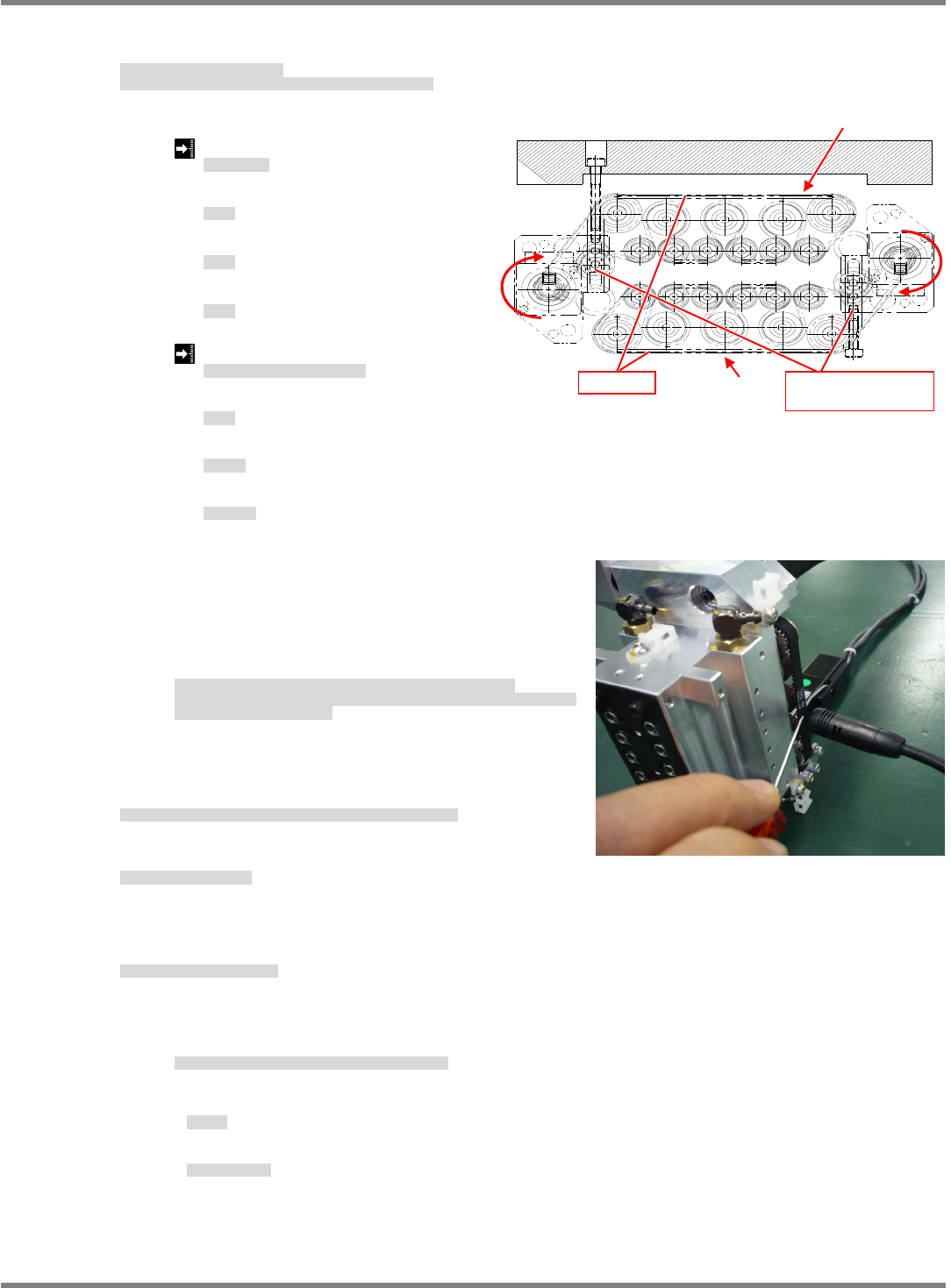
7. Adjust
belt tension.
Pull the T-belt at A and measure tension with ultrasonic tension meter
ベルトテンション調整をします。
T-BELT の A 部を弾き、超音波張力計でテンションを測定します。
调整
皮带张力。
弹 T-BELT 的 A 部,用声波张力计测量张力。
Belt at A/B
A
/B
部ベルト
A/B
部皮带
Maximum value
21N
最大値
最大值
Minimum value
11N
最小値
最小值
14
Average value
18
平均値
平均值
Tension meter setting: Same for A and B
<
張力計設定
> : A / B
部ともに同じ
<
张力计的设定
> : A / B
部都一样
Span: 67 mm
スパン
跨距
Belt width: 6 mm
ベルト幅
皮带宽度
Belt mass: 1.3
g
/m
ベルト質量
皮带质量
Flip the T-BELT at A and measure tension with an
ultrasonic tension meter (two points).
In this case, measure tension at six points in total
while turning the motor shaft in the direction of the
allow shown in the figure below by two turns, and
obtain the maximum, minimum and average values.
T-BELT
の
A
部を弾き、超音波張力計でテンションを測定する。
(2
か所
)
この際、モータ軸を下図の矢印方向に
2
回転づつ送り、計
6
ポイントを測定し、最大
値、最小値、平均値を求めます。
弹
T-BELT
的
A
部,用声波张力计测量张力。
(2
处
)
。
此时,按照下图的箭头方向将电机轴转动两周,测量合计
6
个点,并求出最大值、最小
值、平均值。
8. Attach the
unit, sensors and valves to the head unit.
ヘッドユニッドに、
ユニット / センサ / バルブ関係を取り付けます。
在头装置上安装
装置 / 传感器 / 阀关系。
9. Adjust nozzle
position.
ノズル
位置を調整します。
调整吸嘴
位置。
‘5.2.2 Ball Spline Shaft Replacement’
10. Attach the head unit.
ヘッドユニットを取り付けます。
安装头装置。
‘5.1.1 Head Unit Detaching and Attaching’.
After attaching the head unit, perform the following procedures.
ヘッドユニット取り付け後は、以下の作業を実施します。
安装好头装置以后,进行以下作业。
• Z plane calibration
面補正
Z
面补正
Z
• Jig station
ジグステーション
治具站
NPM-D3
Service Manual
5.3 8-nozzle Head
Page 5-22 EJM6D3-MB-05SM-00(
編集中
).DOC
5.3 8-nozzle Head
8 ノズルヘッド
8 吸嘴头
5.3.1 Z-axis Motor Replacement
Z 軸モータ交換
Z 轴电机的交换
Unit No.
N610067507AA
5.1.1 Head Unit Detaching and
Attaching
ヘッドユニット取り外し
/
取り付け
头装置的拆卸和安装
5.3.1 Z-axis Motor Replacement
Z
軸モータ交換
Z
轴电机的交换
Calibration jig
キャリブレーション治具
校准治具
Z-axis Motor Replacement
Z 軸モータ交換
Z 轴电机的交换
10.
1. Detach the head unit.
ヘッドユニットを取り外します。
卸下头装置。
‘5.1.1 Head Unit Detaching and Attaching’
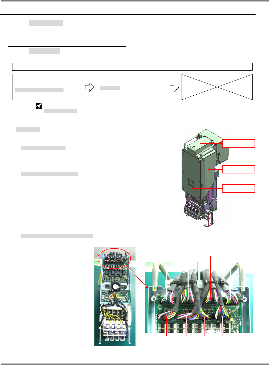
2. Detach the head unit cover. (Fig. 1)
ヘッドユニットカバーを外します。(Fig. 1)
拆下头装置的盖。(Fig. 1)
3. Disconnect wiring from the head unit Z-axis motor. (Fig. 2)
ヘッドユニット Z 軸モータの配線を外します。(Fig. 2)
取下头装置 Z 电机的配线。(Fig. 2)
Fig. 1
Top cover
Side cover
Front cover
CN1
POS1
CN4
POS4
CN3
POS3
CN2
POS2
CN6
POS6
CN7
POS7
CN5
POS5
CN8
POS8
Fig. 2
NPM-D3
Service Manual
5.3 8-nozzle Head
EJM6D3-MB-05SM-00(
編集中
).DOC Page 5-23
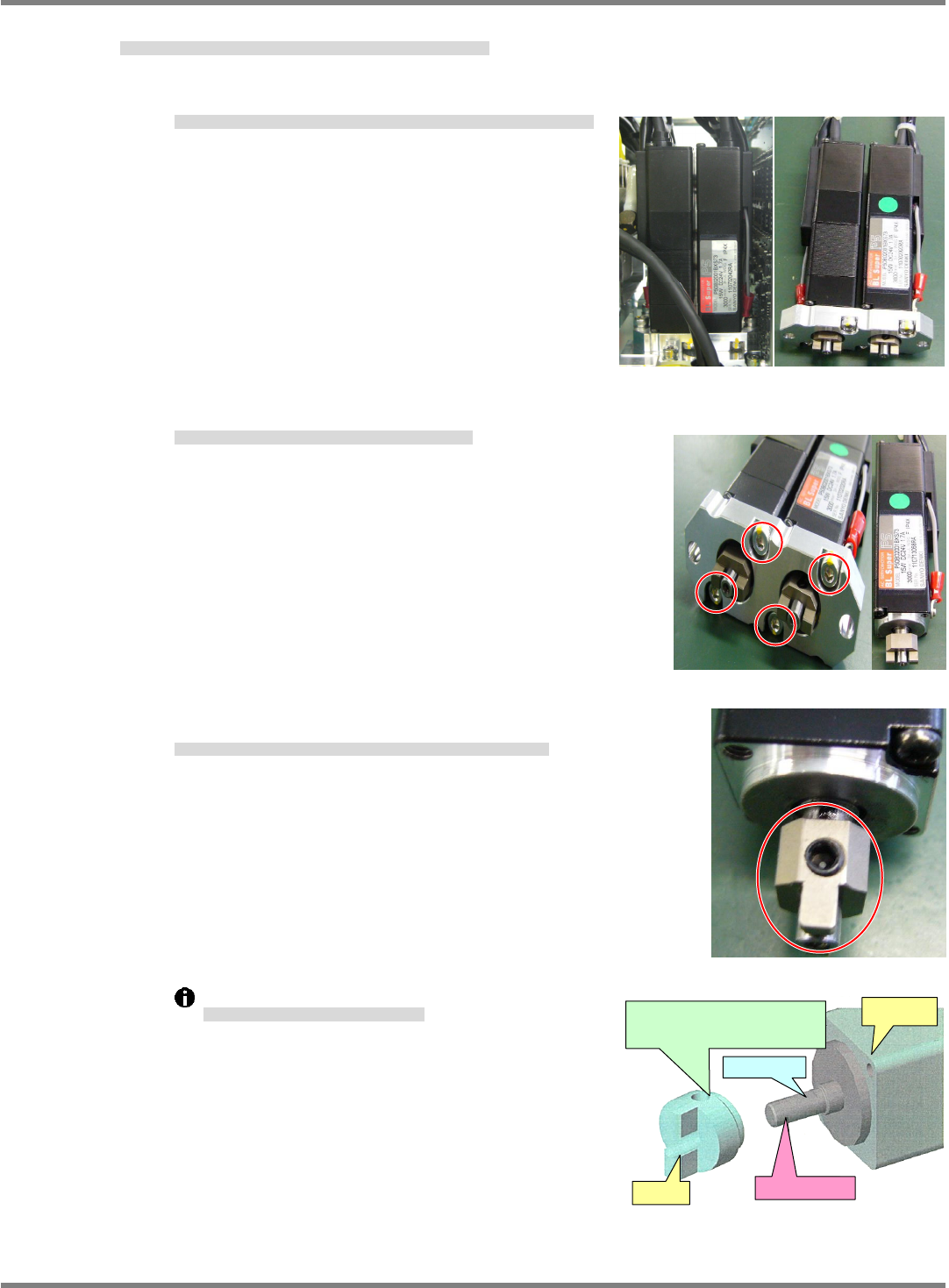
4. Detach the Z-axis motor, install a new motor and couple the joint. (Fig. 3)
Z 軸モータを取り外して、モータを交換しジョイントを取り付けます。(Fig. 3)
卸下 Z 电机后,交换电机,并安装接头。(Fig. 3)
①
Motors are detached by removing the screws (2-M4
16L). (2 motors are detached at a time.)
固定ビス (2-M416L) を外したら、モータが外れます。(モータは 2 個セットで外れます)
拧下固定螺钉 (2-M416L) ,即可卸下电机。(两个电机一起脱落。)
②
Remove the screw (2-3
10L) and detach the motor from the plate.
固定ビス (2-310L) を外し、プレートよりモータを外します。
拧下固定螺钉 (2-310L) 后,从板上卸下电机。
③
Loosen the screw (1-M4
4L), detach the joint, then attach a new
motor.
固定ビス (1-M44L) を緩めてジョイントを外し、交換モータに取り付けます。
拧松固定螺钉 (1-M44L) 卸下接头后,将其安装在交换电机上。
Motor shaft and joint coupling positions
モータシャフトとジョイントの組み合わせ位置
电机轴和接头的组装位置
Fig. 3
Motor
Joint
D-cut
p
lane
Motor shaft
Align the screw hole with the
D-cut plane of the motor.