NPM-D3维修手册.pdf - 第115页
NPM-D3 SERVICE MANUAL 4.6 Optional Units EJM6D3-MB-04SM-02.DOC Page 4-77 Fig. 1 Clamp Bolt Length クランプボルトの長さ 夹紧螺栓的长度 12. 1. Measure the full length of the clamper with a caliper. (Fig. 1) クランパの全長をノギスで測定します。 (Fig. 1) 用游…
NPM-D3
SERVICE MANUAL
4.6 Optional Units
Page 4-76 EJM6D3-MB-04SM-02.DOC
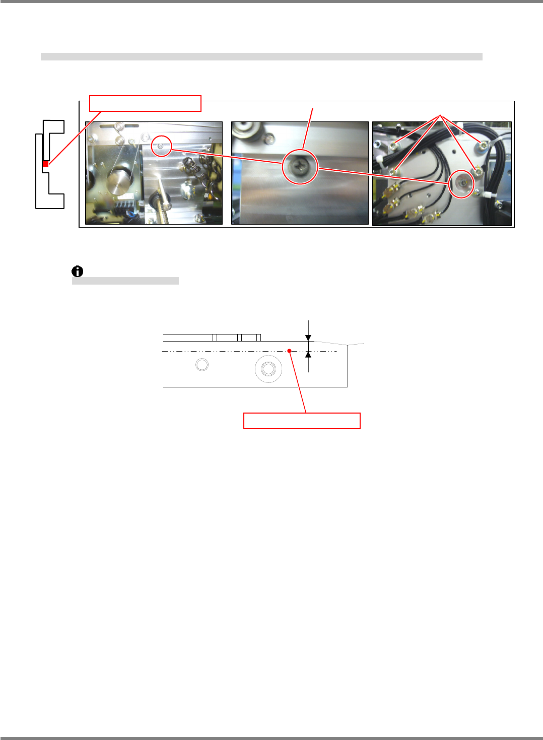
6. If the transfer rail planarity or height is not within the above requirement, the transfer rails can be raised and
lowered by loosening the mounting bolts (3-M5) and lock nut (Front) of the eccentric pin, and then turning
the eccentric pin. (Fig. 3)
測定値が基準値外の場合は、搬送レールの取り付けボルト(3-M5)と偏芯ピンの固定ナット(表側)を緩め、偏芯ピンを回せばレールを上下に調整できます。(Fig. 3)
如测定值在基准值范围以外时,拧松搬送轨道的安装螺栓 (3-M5) 和偏芯销的固定螺母 (正面)、并转动偏芯销,就可将轨道上下调整。(Fig. 3)
Measure the height at the position 2 mm from the end of the guide.
ガイドより
2mm
の位置で測定します。
在离导轨
2 mm
的位置处测定。
Fig. 3
Eccentric pin
4-M5
Adjust with eccentric pin.
2 mm
Measuring point
Photos: NPM-D
NPM-D3
SERVICE MANUAL
4.6 Optional Units
EJM6D3-MB-04SM-02.DOC Page 4-77
Fig. 1
Clamp Bolt Length
クランプボルトの長さ
夹紧螺栓的长度
12.
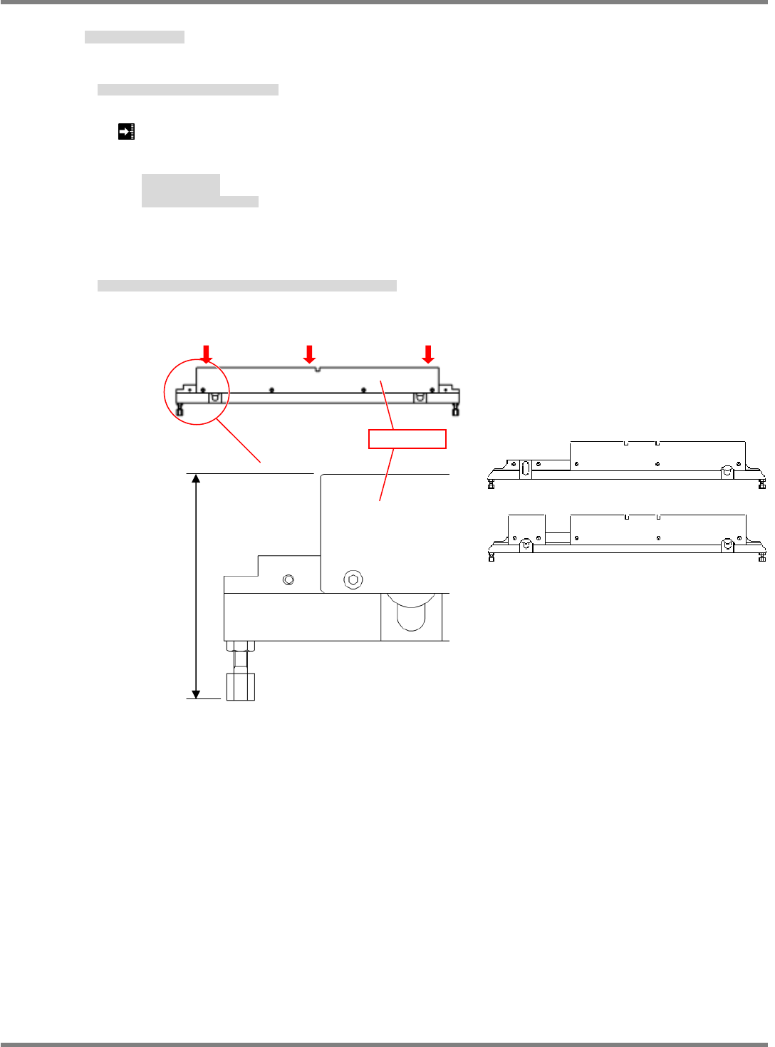
1. Measure the full length of the clamper with a caliper. (Fig. 1)
クランパの全長をノギスで測定します。(Fig. 1)
用游标卡尺测量夹具的全长。(Fig. 1)
Clamper, full length: 66.5
0.02 mm (Left side and Right side)
Clamper, full length: 66.5
0.03 mm (Center)
Clamper, bolt length (Reference value): 17.5 mm
クランパ全長
(
左右
)
クランパ全長
(
中央
)
クランパ部ボルト長さ
(
参考値
)
夹具全长
夹具部螺栓长度
(
参考值
)
2. If the clearance is not within the above requirement, adjust the installed positions of the clamper and the
cylinder.
隙間が基準値外の場合は、クランパとシリンダの取り付け位置を調整します。
间隙在基准值范围以外时,调整夹具和汽缸的安装位置。
250 mm
350 mm
Clamper full length
Right sideCenter Left side
Clamper
NPM-D3
SERVICE MANUAL
4.6 Optional Units
Page 4-78 EJM6D3-MB-04SM-02.DOC
Transfer Rail Parallelism
搬送レール平行度
搬送轨道的平行度
Block gauge set
Dial gauge & magnet stand
ブロックゲージセット
ダイヤルゲージ&マグネットスタンド
块规组件
千分表和磁性支架
13.
1. Detach the retainer plates on the fixed and movable rail sides.
固定側と可動側の押さえプレートを外します。
卸下固定侧和可动侧的按压板。
2. Measure the difference between the rail frame and the guide.
(Fig. 1)
フレームとガイドの段差を測定します。(Fig. 1)
测量架与导轨的高低差。(Fig. 1)
Difference between the frame and the guide: 1.7±0.1 mm
フレームとガイドの段差
架与导轨的高低差
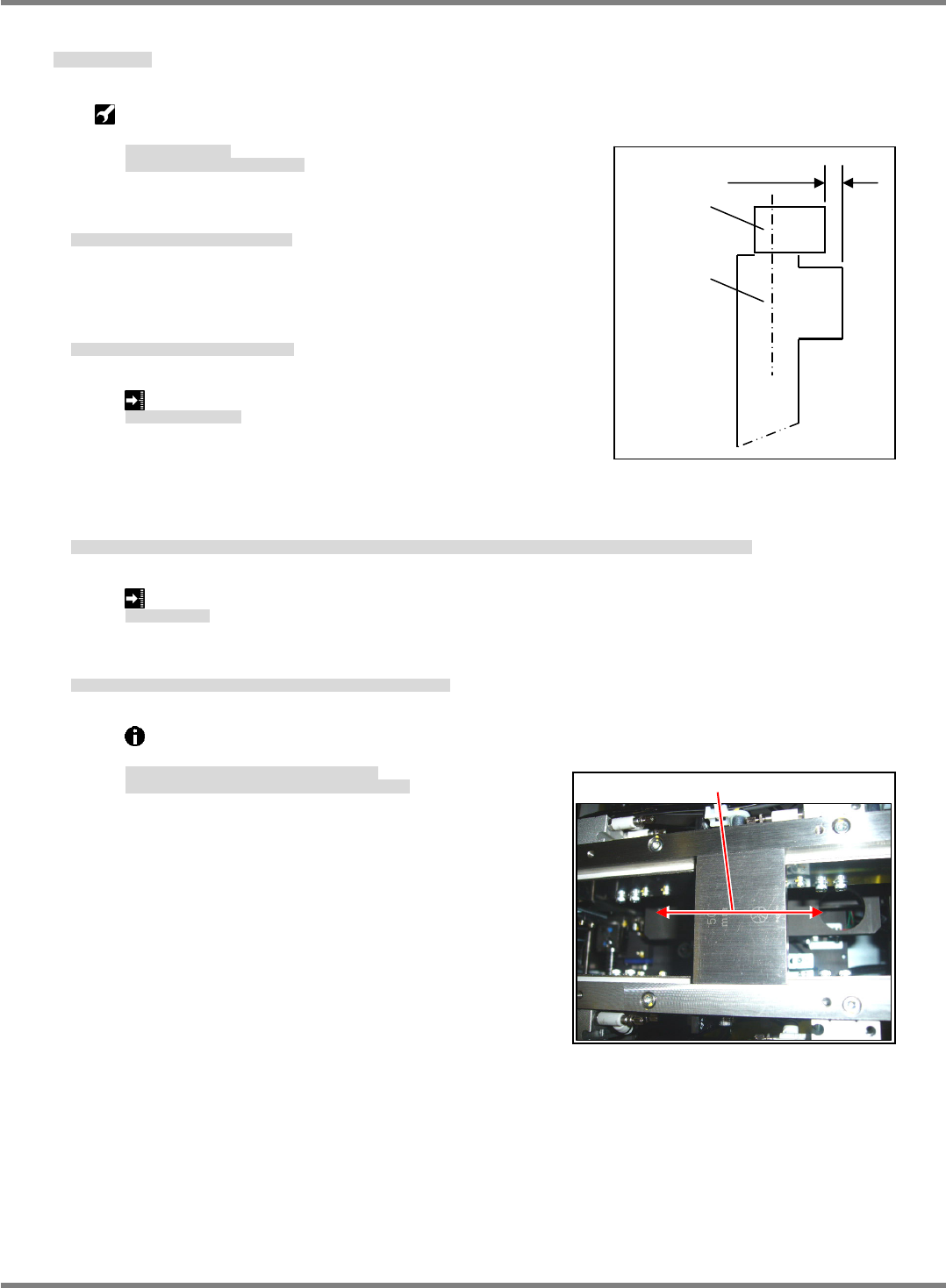
3. Set rail width to 50 mm, insert a block gauge between the rails and check that the width variation across the
full length of the rails meets the requirement. (Fig. 2)
レール幅を 50 mm にし、ブロックゲージをレールの間に入れ、レールの全長について幅のばらつきが基準値内であることを確認します。(Fig. 2)
将轨道宽度调整到 50 mm,将块规放在轨道之间,确认对于轨道的全长宽度,偏差在基准值的范围内。(Fig. 2)
Rail width variation:
0.2 mm
レール幅ばらつき
轨道宽度偏差
4. If the rail width variation is not within the above requirement, adjust the installed positions of the rails.
レール幅のばらつきが基準値外の場合は、ガイドの取り付け位置を調整します。
轨道宽度的偏差不在基准值的范围内时,调整轨道的安装位置。
If the rail width differs between the left and right, adjust it from the timing belt pulley that
interlocks the left and right ball screws.
レール幅が左右で異なる場合は、左右のボールネジを
連結しているタイミングベルトのプーリー部で調整します。
左右边的轨道宽度极端不同时,调整用于连接左右的滚珠丝杠的同步皮带的滑轮部。
1.7
0.1
Guide
Frame
(Fig. 1)
Fig. 2
Move block gauge across the full length of rail.