NPM-D3维修手册.pdf - 第66页
NPM-D3 SERVICE MANUAL 4.3 Feeder Cart Unit Page 4-28 EJM6D3-MB-04SM-02.DOC Fig. 2 Slide the guide to adjust the parallel ism. Stopper Bolt Parallelism Adjustment ストッパーボルト平行度の調整 止动螺栓平行度的调整 Block Dial gauge & magnet …
NPM-D3
SERVICE MANUAL
4.3 Feeder Cart Unit
EJM6D3-MB-04SM-02.DOC Page 4-27
Cart Stopper Bolt Adjustment
交換台車ストッパーボルトの調整
交换台车止动螺栓的调整
Block
Caliper
ブロック
ノギス
块
游标卡尺
10.
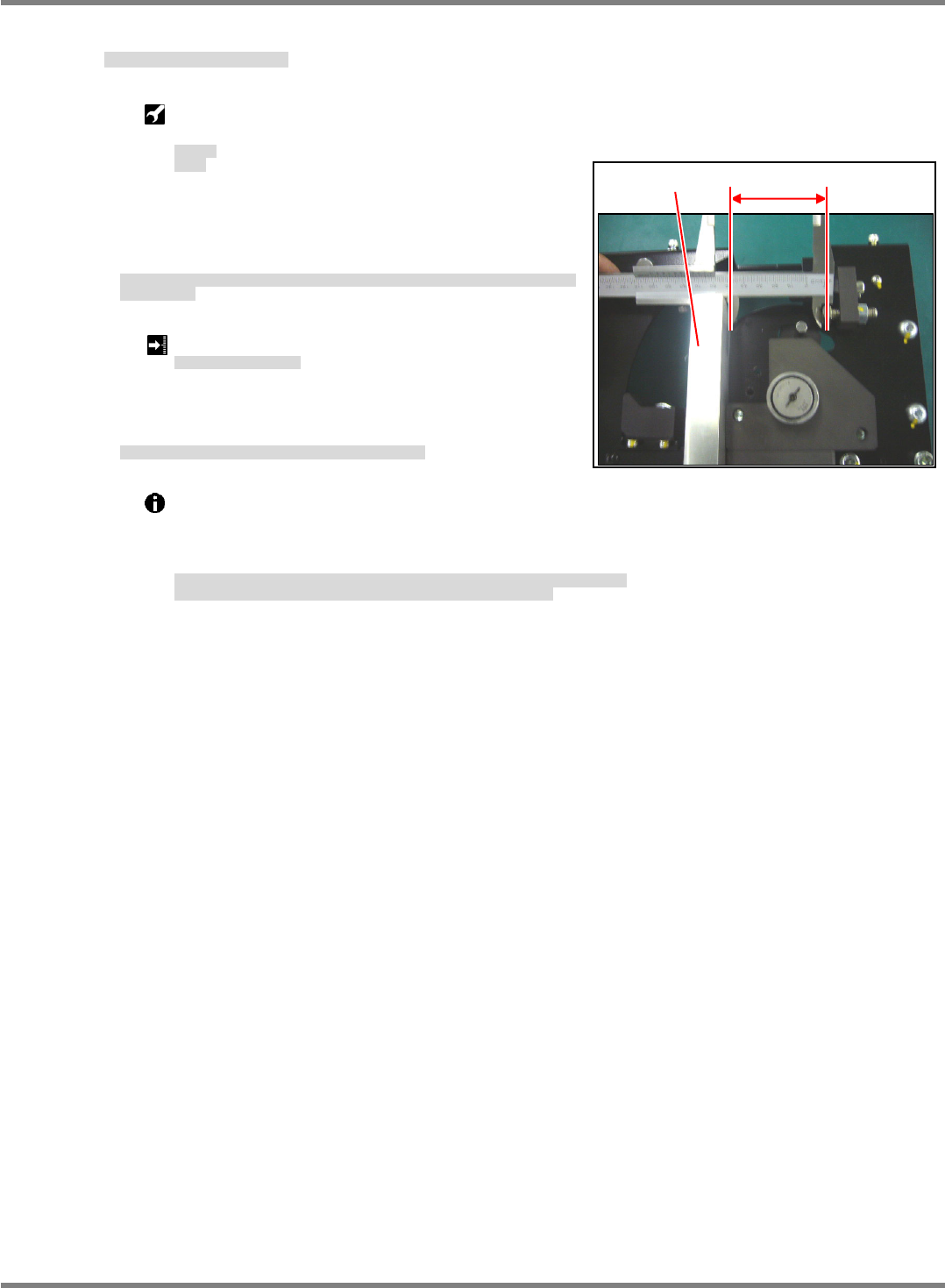
1. Press the block against the side face of the fulcrum block.
Measure the penetration depth of the stopper bolt into the
block contact surface. (Fig. 1)
支点ブロックの側面にブロックを当て、ブロックの当り面とストッパーボルト先端の寸法を測定
します。(Fig. 1)
将块接触到支点块的侧面,测量块的接触面和止动螺栓端部的尺寸。(Fig. 1)
Tray stopper bolt: 61
0.2 mm
交換台車ストッパーボルト
交换台车止动螺栓
2. If the penetration depth of the stopper bolt does not meet
the requirement, adjust it.
基準値外の場合は、ストッパーボルトのねじ込みを調整します。
不在基准值的范围内时,调整止动螺栓的拧紧量。
Before adjusting the stopper bolt position, complete
‘Cart Positioning Plate Clearance Adjustment’ on the preceding page.
If the guide is released, the block presses against the fulcrum block, making it possible to
measure dimensions accurately.
ストッパボルトの位置調整の前に、「■台車規正プレートすき間の調整」を完了しておくこと。
ガイドを外せばブロックが支点ブロックに密着し、正確な寸法を測定できます。
在调整止动螺栓的位置之前,请务必完成前项的「■调整台车调整板间隙」。
如果卸下导轨,块则靠紧在支点块上,由此可以测量正确的尺寸。
Fig. 1
610.2
Block
NPM-D3
SERVICE MANUAL
4.3 Feeder Cart Unit
Page 4-28 EJM6D3-MB-04SM-02.DOC
Fig. 2
Slide the guide to adjust the parallelism.
Stopper Bolt Parallelism Adjustment
ストッパーボルト平行度の調整
止动螺栓平行度的调整
Block
Dial gauge & magnet stand
ブロック
ダイヤルゲージ&マグネットスタンド
块
千分表和磁性支架
Stopper bolt parallelism:
0.02 mm
ストッパボルト平行度
止动螺栓平行度
11.
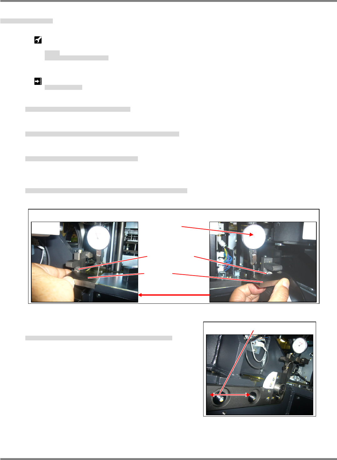
1. Attach a dial gauge to the X-axis using the magnet stand.
X軸にマグネットスタンドでダイヤルゲージを取り付けます。
用磁性支架,在 X 轴上安装千分表。
2. Set the block on the stopper bolt tip on the drive side, contact with the dial gauge and set 0.
駆動側のストッパボルト先端にブロックを置き、ダイヤルゲージを当て、0セットします。
在驱动侧的止动螺栓端部上放置块,贴上千分表,设定为 0。
3. Move the dial gauge attached to the X-axis to the guide side.
X軸に取り付けているダイヤルゲージをガイド側に移動させます。
将 X 轴上安装的千分表移动到导轨侧。
4. Set the block on the stopper bolt tip and measure the parallelism of the stopper bolt on the drive side using
the dial gauge. (Fig. 1)
ストッパボルト先端にブロックを置き、ダイヤルゲージで駆動側との平行を測定します。(Fig. 1)
在止动螺栓端部上放置块后,用千分表测量与驱动侧之间的平行度。(Fig. 1)
5. If the parallelism does not meet the requirement, slide the
guide back and forth to adjust the parallelism. (Fig. 2)
平行度が基準値外の場合は、ガイドを前後にスライドさせ平行度を調整します。(Fig. 2)
平行度不在基准值范围内时,将导轨前后滑动,调整平行度。(Fig. 2)
Fig.1
Block
Stopper bolt
Guide side
Set 0.
Drive side
NPM-D3
SERVICE MANUAL
4.3 Feeder Cart Unit
EJM6D3-MB-04SM-02.DOC Page 4-29
4.3.2 Feeder Cart Connection
交換台車接続
交换台车的连接
Unit No.
N610073093AA
4.3.1 Feeder Cart Handling Unit
交換台車駆動ユニット
交换台车驱动装置
4.3.2 Feeder Cart Connection
交換台車接続
交换台车的连接
Connector positioning jig
コネクタ位置調整治具
连接器位置调整治具
Feeder Cart Connector Position Adjustment
交換台車コネクタ位置調整
调整交换台车的连接器位置
12.
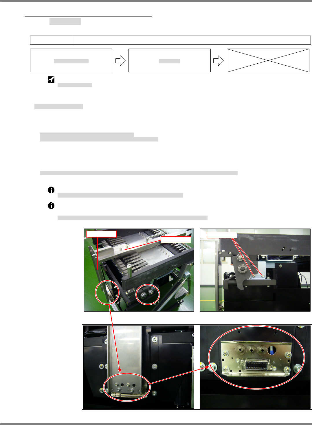
1. Insert the jig base into slot No. 9 on the feeder block.
Insert the jig plate into the connector and assemble to the jig base. (Fig. 1)
フィーダ搭載部の 9 番スロットに治具ベースを挿入します。
コネクタ部に治具プレートを挿入し、治具ベースと組み合わせます。(Fig. 1)
在料架搭载部的第 9 号插槽中插入治具基座。
在连接器部插入治具板后,并与治具基座组装。(Fig. 1)
2. If the jig base and jig plate do not mate, adjust the height, tilt, forward-reverse position and right-left position
of the connector installation bracket.
治具ベースと治具プレートが組み合わさらない場合は、コネクタ取り付け部の高さ、前後、左右、傾きをそれぞれ調整します。
不能组装治具基座和治具板时,分别调整连接器安装部的高度、前后、左右、以及倾斜度。
Adjust the connector height and forward-reverse position from the coupling bracket. (Fig. 2)
コネクタの高さ、前後方向については、連結ブラケット部で調整します。
(Fig. 2)
关于连接器的高度、前后方向,在连接托架部进行调整。
(Fig. 2)
Fine-adjust the connector right-left position, tilt and height from the front connector installation
bracket. (Fig. 3)
コネクタの左右、傾きと高さ方向の微調整は、前面のコネクタ取り付け部で調整します。
(Fig. 3)
关于连接器的左右、倾斜度以及高度方向的微调整,在前面的连接器安装部进行调整。
(Fig. 3)
Fig. 3
Fig. 1
Jig base
Jig plate
Fig. 2
Fixed parts